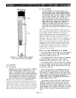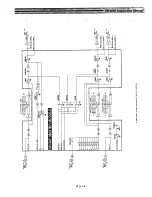
118. GROUP INSERT 1-8 (IN, OUT)
These phone jacks serve as a patch point for the
signal from the correspondingly numbered group
mixing bus. Nominal output and input level is +4
dBu (1.23 V).
The OUT jacks may be used as auxiliary group
outputs to another console or as a group output to a
multitrack tape machine, although the direct
output connectors are provided for this purpose
[103]. They are most often likely to be used for
sending the input channel signal to an auxiliary
signal processors (compressors, graphic EQs, noise
gates, etc). INSERT OUT is always "live" whether
or not the group output is on.
The IN jacks apply signal to the group busses and
are “normalled” so that inserting a plug interrupts
the internal signal flow through the bus, instead
bringing in the return from an auxiliary signal
processor. However, there is an INSERT on/off
switch in each bus [43] which can bypass the
INSERT IN jack, regardless of whether an external
source is plugged in or not.
119. MTRX INSERT 1-8 (IN, OUT)
These phone jacks serve as a patch point for the
signal from the correspondingly numbered matrix
mixing bus. They function identically to the insert
points for the group mixing bus [118], and are
located in the mixed matrix signal path (including
sub-in) ahead of the insert on/off point and master
level control.
120. ST INSERT L (IN, OUT)
These phone jacks serve as a patch point for the
signal from the left side of the stereo mixing bus.
Nominal output and input level is +4 dBu (1.23 V).
They function just like the Group Insert jacks
[118], except they affect the main stereo output
instead of the group output.
121. ST INSERT R (IN, OUT)
These phone jacks are just like the ST INSERT R
jacks [120], except the affect the right side of the
stereo mixing bus.
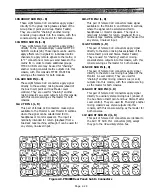
Figure 2-10. PM4000 Rear Panel: Group, Matrix and Stereo Insert In/Out Connectors
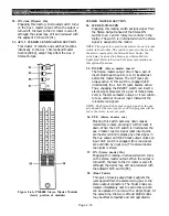
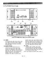
Figure 2-11 PM4000 Rear Panel: Aux Insert In/Out Connectors
Page 2-30
Summary of Contents for PM4000
Page 1: ...PROFESSIONAL AUDIO MIXING CONSOLE PM4000 OPERATING MANUAL YAMAHA ...
Page 2: ...PM4000 OPERATING MANUAL ...
Page 7: ...Section 1 Introduction ...
Page 11: ...Section 2 Brief Operating Instruction ...
Page 47: ...Section 3 Specifications ...
Page 51: ...Dimensional Drawings PM4000 Console all versions Page 3 4 ...
Page 52: ...Page 3 5 ...
Page 53: ...Page 3 6 PM4000 Console Rear Profiles ...
Page 54: ...Module Block Diagrams See back of the manual for overall system block diagram Page 3 7 ...
Page 55: ...Page 3 8 ...
Page 56: ...Page 3 9 ...
Page 57: ...Page 3 10 ...
Page 58: ...Page 3 11 ...
Page 59: ...Page 3 12 ...
Page 60: ...Section 4 Installation Notes ...
Page 72: ...Figure 4 13 Cables For Use With Balanced Sources Page 4 12 ...
Page 79: ...SECTION 5 Gain Structure and Levels ...
Page 82: ...Figure 5 1 Dynamic Range and Headroom in Sound Systems Page 5 3 ...
Page 86: ...Section 6 Optional Functions ...
Page 106: ...Section 7 Operating Notes and Hints ...
Page 119: ...Section 8 Applications ...
Page 127: ...Section 9 Maintenance ...
Page 131: ......
Page 132: ...YAMAHA VN02300 ...

