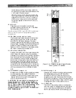
This locking switch assigns the channel output
directly to the stereo bus. An LED in the switch
turns on when the signal is assigned to the stereo
bus. If you want the cleanest, quietest stereo mix,
create it by assigning inputs directly to the stereo
bus with this switch rather than running signal
to group busses and then mixing the groups down
to stereo.
1. 1 2 3 4 5 6 7 8 (ASSIGN switches)
These locking switches assign the channel output
to group mixing busses 1 through 8. An LED
indicator in each switch turns on when the signal
is assigned to the bus.
2. PAN (switch & rotary control)
The locking PAN switch activates the PAN pot so
you can use it to position signal between any odd-
numbered and even-numbered group mixing
busses (provided the corresponding ASSIGN
switches are engaged). This lets you create up to
four additional stereo mixes. An LED in the
switch turns on when the PAN switch is engaged.
Center position applies 3 dB less signal to each
bus than the level obtained with full left or right
assignment so that the combined stereo signal
across a given pair of busses adds up to constant
power at all PAN pot positions.
3. ST (Stereo)
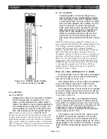
Figure 2-1a. PM4000 Standard Input
Module (upper portion of module)
Section 2.
Brief Operating Instructions
2.1 PM4000 Front Panel
Features
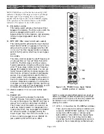
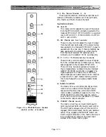
NOTE: Features are numbered to correspond with the
numbers on these module drawings. In the case of the
input modules, where the standard monaural module
and stereo modules are similar, we have used the same
feature number where the features are identical. Where
the features are not identical, we have used an “S” suffix.
For example, feature [4] is the 48V phantom power
switch in both the monaural and the stereo input
modules, but the PAN switch and pot [2] on the stan-
dard input module is not the same as the BAL/PAN
switch, and the concentric selector switch and pot [2S]
on the stereo input module.
2.1.1 The Standard Monaural Input Module
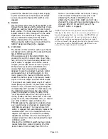
4. +48V
This switch turns phantom power on and off at
the channel’s XLR input connector. Power can be
turned on, however, only if the MASTER PHAN-
Page 2-1
Summary of Contents for PM4000
Page 1: ...PROFESSIONAL AUDIO MIXING CONSOLE PM4000 OPERATING MANUAL YAMAHA ...
Page 2: ...PM4000 OPERATING MANUAL ...
Page 7: ...Section 1 Introduction ...
Page 11: ...Section 2 Brief Operating Instruction ...
Page 47: ...Section 3 Specifications ...
Page 51: ...Dimensional Drawings PM4000 Console all versions Page 3 4 ...
Page 52: ...Page 3 5 ...
Page 53: ...Page 3 6 PM4000 Console Rear Profiles ...
Page 54: ...Module Block Diagrams See back of the manual for overall system block diagram Page 3 7 ...
Page 55: ...Page 3 8 ...
Page 56: ...Page 3 9 ...
Page 57: ...Page 3 10 ...
Page 58: ...Page 3 11 ...
Page 59: ...Page 3 12 ...
Page 60: ...Section 4 Installation Notes ...
Page 72: ...Figure 4 13 Cables For Use With Balanced Sources Page 4 12 ...
Page 79: ...SECTION 5 Gain Structure and Levels ...
Page 82: ...Figure 5 1 Dynamic Range and Headroom in Sound Systems Page 5 3 ...
Page 86: ...Section 6 Optional Functions ...
Page 106: ...Section 7 Operating Notes and Hints ...
Page 119: ...Section 8 Applications ...
Page 127: ...Section 9 Maintenance ...
Page 131: ......
Page 132: ...YAMAHA VN02300 ...


