background image

PM1D System Software V1.6 Supplementary Manual

12

Hint

If a PS/2 keyboard is connected to the CS1D, you 
can also type Ctrl + U to input the highlighted “U” 
character. (As a shortcut, you can hold down the 
Ctrl key and type the first character of the button 
name in the character palette.)

When you input the highlighted “U,” no further 
characters can be input into the text box. Also, any 
previously-input characters will be deleted.

To delete the highlighted “U,” click the CLEAR 
button.

5. Click the ENTER button at the right of the charac-

ter palette.

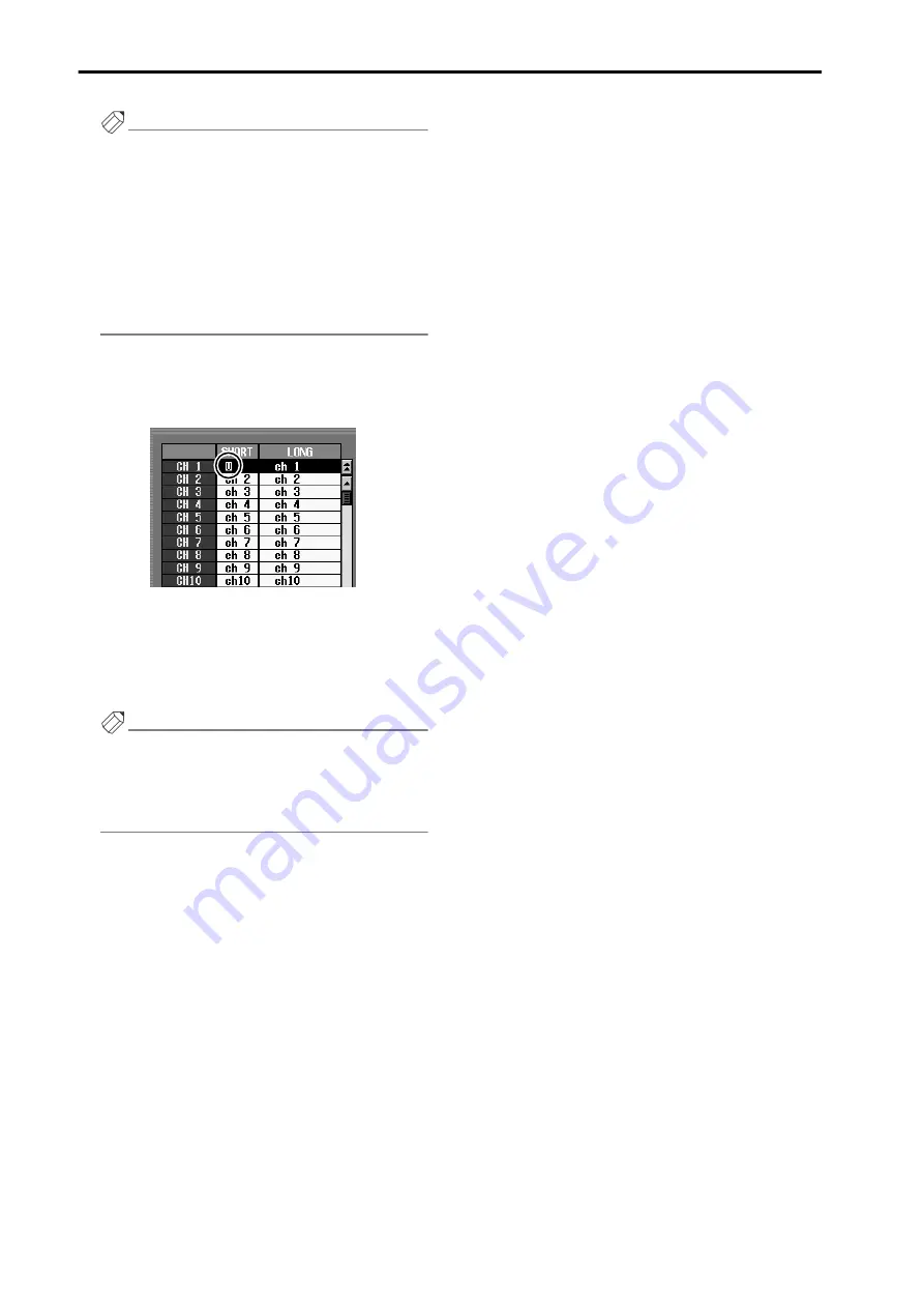
A highlighted “U” character will be input in the short 
name field of the name list.

The Auto Naming function is now enabled for the 
corresponding input channel. Now the port name 
assigned to the channel will always be displayed in 
areas of the screen that display the short name of the 
corresponding channel, and in the corresponding 
INPUT [NAME] indicator of the panel.

Hint

It is also possible to select the long name field instead 
of the short name field in step 3. In this case, the port 
name will always be displayed in areas of the screen 
that display the long name of the corresponding 
channel.

Summary of Contents for PM1D Manager V2

Page 1: ...E E PM1D System Software V1 6 Supplementary Manual ...

Page 2: ...aha Corporation is prohibited Trademarks Company names and product names are trademarks and registered trademarks of their respective owners Symbols such as and TM are not explicitly given in this document The illustrations and LCD screens as shown in this owner s manual are for instructional purposes only and may appear somewhat different from those on your instrument ...

Page 3: ...or and gate 21 Clear Library 22 Extended functionality for the attenuators 23 Global Channel Copy 24 CH COPY screen 24 Using the Global Channel Copy function 25 Input Meter Bridge 27 FIXED CH mode 28 FOLLOW PANEL mode 31 Parameter Lock Console Lock 33 SECURITY screen 33 Setting the System Password Console Password 34 Parameter Lock 35 Console Lock 36 Surround panning 37 SURR PRM screen 37 Internal...

Page 4: ... scene is recalled Selective Recall p 18 A Selective Recall function has been added allowing you to specify for each scene parameters channels that will be excluded from recall when that scene is recalled Extended functionality for Recall Safe p 21 The Recall Safe function has been extended resulting in slight changes to the Recall Safe screen and add ing parameters that can be set to Recall Safe ...

Page 5: ... following improvements have been made to the new functions that were added in V1 5 Panel Assign in the ST IN block In V1 5 a PANEL ASSIGN screen was added to the UTILITY function allowing the combination of input channels and ST IN channels reflected in the panel to be specified for each individual block ...

Page 6: ...removed in V1 6 For example any two ST IN channels of consecutive number such as ST IN channels 1 2 and 5 6 or 1 2 and 7 8 can be combined freely Also if necessary you may assign combinations of the same ST IN channel to upper and lower ST IN blocks e g ST IN channels 1 2 and 1 2 or ST IN channels 5 6 and 5 6 1 2 3 4 3 4 1 2 5 6 7 8 7 8 5 6 ST IN block 2 ST IN block 1 ST IN block 2 ST IN block 1 S...

Page 7: ...the screen the name of the port assigned to that channel would be displayed instead of the short name of the input channel shown in the screen In V1 6 when you turn on the UNIT NAME button in the NAME MODE area the INPUT NAME indicator in the INPUT block will also show the name of the port assigned to that channel SEL THR COMP THR CLIP 6 12 18 30 60 GATE THR COMP THR GATE SEL THR COMP THR GATE SEL...

Page 8: ...reen of the PAN ROUTING function Channel name area If the CH NAME button located in the NAME MODE area at the bottom of the display is turned on this area will show the short name of the corresponding channel EQ CH screen LCR screen When the UNIT NAME button is on the name of the port assigned to that channel will be displayed EQ CH screen LCR screen Short name of the input channel Short name of t...

Page 9: ...he name assigned to each DCA group In V1 6 the channel names of the last assigned two channels can also be displayed in the DCA NAME indi cator This is called the DCA auto naming function DCA auto naming procedure The auto naming procedure is as follows 1 Access the IN PATCH OUT PATCH function NAME screen DCA name 1 2 3 4 ...

Page 10: ...sponding DCA group At this time the DCA NAME indicator will go dark if a channel has not been assigned to the corresponding DCA group 6 As necessary perform the same operation for other DCA groups 7 Assign channels to the DCA groups for which you performed steps 3 6 For example if you assign input channels 1 and then 2 to DCA group 1 the corresponding DCA NAME indicator will show the channel names...

Page 11: ...ming procedure The auto naming procedure is as follows 1 Access the IN PATCH OUT PATCH function NAME screen 2 In the LIST SELECT area 1 move the cursor to the INPUT button and press the ENTER switch The name list 2 will show a list of the short names four characters and long names eight characters assigned to each input channel 3 In the name list select the desired input channel and move the curso...

Page 12: ... button 5 Click the ENTER button at the right of the charac ter palette A highlighted U character will be input in the short name field of the name list The Auto Naming function is now enabled for the corresponding input channel Now the port name assigned to the channel will always be displayed in areas of the screen that display the short name of the corresponding channel and in the corresponding...

Page 13: ...B when panned to the center and at nominal level when panned fully left or right L63 or R63 2 Move the cursor to the L R button and press the ENTER switch A popup window will ask you to confirm the changed Pan Nominal setting 3 Move the cursor to the OK button and press the ENTER switch 4 Enable pairing for the desired channels and make sure that a mode other than BALANCE is selected as the pan mo...

Page 14: ...0 dB DCA Unity procedure To use this option access the MONI CUE function CUE SOLO screen and turn on the DCA UNITY ON OFF button that has been added to the DCA area If this button is on pressing the DCA CUE button allows you to monitor that DCA group at unity level regardless of the current position of the DCA fader or the on off state of the DCA MUTE switch Hint The setting of the DCA UNITY ON OF...

Page 15: ...al device when that scene is recalled or automatically start the transport of an external device Scene Link Event procedure Here s how to program MIDI events for each scene 1 Access the SCENE function MEMORY screen 2 In the list click the row for the desired scene to select it You cannot program MIDI events for a READ ONLY scene or a protected scene 3 Click the STORE button in the lower left of th...

Page 16: ...ill be added to the COMMENT MIDI EVENT field Also characters in the characters palette other than 0 9 and A F will be grayed out and will be unavailable for input 7 Use the 0 9 and A F characters of the character palette to directly input the MIDI event in hexadec imal format Two hexadecimal characters correspond to one byte of the MIDI message 8 When you have finished inputting the MIDI event cli...

Page 17: ...LENGTH OVER will be displayed and you will not be able to press the STORE button Delete characters until the warning is no longer displayed You cannot input FE Active Sensing as a MIDI code While inputting the MIDI event you can click the EVENT CODE SET button and insert the event that specifies the output destination This lets you output events to different MIDI OUT connectors ƒEven if you recall...

Page 18: ...hat will be recalled or conversely a combination of parameters channels that will be excluded from the recall operation This lets you create partial scene images for store recall using them in a way similar to libraries So that you can universally enable disable the Selective Recall function settings saved in each scene a BYPASS button has been added to the MEMORY screen SELECTIVE RECALL FUNCTION ...

Page 19: ...for which this function can be set are the same as in the SCENE function RECALL SAFE screen 4 RECALL PARAMETER SELECT button SAFE PARAMETER SELECT button This button selects the parameter that will be affected The function of this button will change depending on the button you select in the SELEC TION MODE area 1 If RECALL PARAMETER is on This button will function as the RECALL PARAME TER SELECT b...

Page 20: ... prior to recall However if two channels are paired in the current scene and only one of these channels is set to Safe by the Selective Recall settings of the scene you are recalling recalling that scene will cause both channels to be Safe and the state prior to recall will be maintained If MIX channels set to Selective Recall have dif fering mix types VARI or FIX before and after recall the mix t...

Page 21: ... Safe function of prior versions has been extended as follows Recall Safe is now possible for compressor and gate Compressor and gate have been added to the parameters for which you can make Recall Safe settings Accordingly the SCENE function RECALL SAFE screen has been redesigned as follows ...

Page 22: ...tton to erase the library returning it to a blank state If the FOLLOW SCENE button of the LIBRARY PROTECTION area added to the PREFERENCE screen from V1 6 is turned on p 48 libraries that are linked to a scene cannot be erased If you attempt to recall a warning message will appear If this preference item is off a library can be erased even if it linked to a scene However in this case the library n...

Page 23: ... rapidly set the attenuator for each input channel a dedicated ATT screen for setting the attenuators has been added to the INPUT EQ function In conjunction with this change the ATTENUATOR encoder display in the SELECTED INPUT CHANNEL has been changed as follows Range of 96 dB to 0 dB Same display method as previous Range of 1 dB to 24 dB The 0 dB LED will remain lit and the LEDs at the 96 dB side...

Page 24: ...rently selected channel and copy them to multiple channels of the same type in a single operation This function is called Global Channel Copy CH COPY screen To allow you to use the Global Channel Copy function a CH COPY screen has been added to the IN CH VIEW function and to the OUT CH VIEW function 1 2 3 6 5 1 4 2 3 6 5 ...

Page 25: ...the CH COPY screen of the IN CH VIEW or OUT CH VIEW function 2 Press a SEL switch to select the desired copy source input channel or output channel Alternatively you can select the copy source by click ing a SEL button in the screen to access the CHAN NEL SELECT popup window If you change the copy source all settings in the PARAMETER SELECT area and the DESTINA TION CH SELECT area will be cancelle...

Page 26: ...n will you also be able to choose whether send levels for signals sent from input channels to the MIX bus will be copied as well To make this setting use the following two buttons located at the left of the ALL button WITHOUT MIX SEND button If this button is on the send level of signals sent from each input channel to the corresponding MIX bus will not be copied WITH MIX SEND button If this butto...

Page 27: ...d from within the screen or from the panel A METER BRIDGE area has been added to all screens of the METER function allowing you to switch the meter bridge display However the MIX 1 48 screen and MATRIX 1 24 ST MONITOR screen do not show the FIXED CH button and FOLLOW PANEL button explained below CH 1 48 STIN 1 4 screen MATRIX 1 24 ST MONITOR screen ...

Page 28: ...ls displayed in the meter bridge will always be fixed Horizontal pairing mode Vertical pairing mode Use the following buttons to select the combination that is displayed button Selectable only if the FIXED CH button is on When this button is on the meters will always display the levels of input channels 1 48 if Vertical pairing mode is selected channels 1 49 2 50 24 72 regardless of the currently ...

Page 29: ...26 74 48 96 regardless of the currently selected panel assignment or layer Horizontal pairing mode Vertical pairing mode At this time the MIX MATRIX bus number LED located at the bottom of the meter bridge will go dark In the METER section the METER SELECT MIX 25 48 switch will go dark and the MATRIX 1 24 switch will blink You can also hold down the top panel SHIFT switch and press the METER secti...

Page 30: ...n will automati cally turn on button When this button is on the forty eight meters at left and right will display the output levels of MIX channels 1 48 This button is linked with the METER section METER SELECT MIX 25 48 switch At this time the MIX MATRIX bus number LED located at the bottom of the meter bridge will light In the METER section the METER SELECT MIX 25 48 switch will light and the MA...

Page 31: ...PANEL button is on When this button is on the forty eight meters at left and right will display the input levels of the input channels cur rently assigned to INPUT blocks 1 4 At this time the MIX MATRIX bus number LED located at the bottom of the meter bridge will go dark In the METER section the METER SELECT MIX 25 48 switch will blink and the MATRIX 1 24 switch will go dark FOLLOW PANEL button i...

Page 32: ...utton The same display will appear as when the ST IN button is turned on in FIXED CH mode button The same display will appear as when the MIX button is turned on in FIXED CH mode button The same display will appear as when the MATRIX button is turned on in FIXED CH mode While the meter bridge shows the input channel or ST IN channel levels the panel switches in the METER section will operate diffe...

Page 33: ...u to use the Parameter Lock and Console Lock functions Specifying the console password allows you to use only the Console Lock function SECURITY screen A SECURITY screen has been added to the UTILITY function allowing you to input passwords and enable or defeat Parameter Lock or Console Lock 1 SYSTEM PASSWORD This specifies the password for the entire system When using DUAL CONSOLE mode the system...

Page 34: ... input the current password into the AUTHORIZATION popup window that appears when you click SYS TEM PASSWORD and then execute steps 2 5 If you want to remove the password input the cur rent password into the AUTHORIZATION popup window that appears when you click SYSTEM PASSWORD then execute steps 2 5 with NEW PASSWORD and CONFIRM PASSWORD left blank and click the OK button 3 Make sure that the cur...

Page 35: ...e of SOME PARAMETERS WERE LOCKED will appear at the bottom of the screen If in this state you attempt to modify locked parame ters in the screen or on the panel a warning message will appear If you are using DUAL CONSOLE mode the message will appear only on the console that was operated Even if parameters are locked recalling a scene will generally disable the lock and the settings will be overwri...

Page 36: ...TION popup win dow will appear asking you to input the password 3 Input the appropriate password and click the OK button The following screen will appear and the faders con trols and keys of the console will no longer be opera ble Be aware that the cursor keys or ENTER key of the panel cannot be used to defeat Console Lock Hint While the console is locked all display components of the panel will g...

Page 37: ...surround parameters and per form surround panning operations 1 SEL channel select Selects the input channel ST IN channel for which you will perform surround panning In the SURR PRM screen you can set surround parameters in units of two channels 2 Channel number name Indicates the number and short name or unit name of the channel 3 Pairing Indicates the pairing status of the selected channels You ...

Page 38: ...ront left C front center R front right Ls rear left Rs rear right and LFE subwoofer 6 1ch This mode uses seven channels the channels of 5 1ch and a Bs rear center channel 6 Level meters These meters indicate the master level of the sur round buses Be aware that the level meters in the SURR PRM screen show the final levels of the surround buses they do not show the send levels that are being sent f...

Page 39: ...and the F knob and R knob values will be linked If 3 1ch or 5 1ch are selected as the surround mode the screen will show only a knob that adjusts the front divergence If surround mode 3 1ch or 5 1ch 8 LFE Low Frequency Effects knob Adjusts the output level of the signal sent from the input channel to the LFE Low Frequency Effects bus for the subwoofer The signal sent from the input channel to the ...

Page 40: ...nd channel output destination For example if 6 1ch is selected as the surround mode the surround panning signal flow will be as follows Signal flow when surround mode 6 1ch Surround mode MIX bus 17 MIX bus 18 MIX bus 19 MIX bus 20 MIX bus 21 MIX bus 22 MIX bus 23 MIX bus 24 3 1ch L R C S Front left Front right Front center Surround 5 1ch L R C Ls Rs LFE Front left Front right Front center Rear lef...

Page 41: ...the R knob displayed in the DIVERGENCE area 5 LFE 5 1ch 6 1ch only This encoder controls the send level of the signal sent from the currently selected channel to the LFE sur round bus MIX bus 24 Turning the encoder toward the right increases the value If the surround mode is 6 1ch or 5 1ch this is linked with the LFE knob displayed in the LFE area of the SURR PRM screen While surround mode is acti...

Page 42: ...not possible to pair MIX buses 17 24 while surround mode is active 2 VARI FIX indicator The VARI FIX indicator of MIX buses 17 24 will indicate SURR This setting cannot be changed while surround mode is active 3 Send level The knob and value box indicate the send level of the signal that is sent from the input channel ST IN channel to MIX buses 17 24 This value is calculated based on the current s...

Page 43: ...urn red while you are dragging it Using the cursor switches Move the cursor to the surround pan grid of the channel you want to control and press the ENTER switch Alternatively click within the grid and then press the ENTER switch The symbol will turn red In this state you can press the CURSOR switches to move the surround panning in the left right direction or press the CURSOR switches to move th...

Page 44: ...gence for the rear LFE If the surround mode is 5 1ch or 6 1ch you can adjust the signal level that is sent to the LFE bus Use the LFE knob in the screen or SELECTED INPUT CHANNEL section MIX SEND LEVEL PAN encoder 24 Pattern 1 The channels will move in the same direction for front rear and left right movement Pattern 2 The channels will move in oppo site directions front rear and in the same direc...

Page 45: ...l non paired input channel library the PAT TERN LINK button setting will remain on and only the other channel will be recalled Subsequent operation will function according to the LINK set ting Channel copy When you perform panel operations to copy an input channel surround related parameters will also be copied However PATTERN LINK settings will be copied only if the copy source channel is paired ...

Page 46: ...he three bands low mid and high has been added as an effect type for the internal effects This effect type is stored in effect library No 30 If a library using this effect type is recalled SOLO buttons LOW MID HIGH will be displayed in the center of the screen These buttons allow you to solo each of the frequency divided bands For details on the other parameters refer to p 49 ...

Page 47: ... the UPLOAD button or DOWNLOAD button the PM1D will start up in normal mode Transfer of the scenes and all libraries will begin and the PROGRESS popup window will appear indicat ing the progress status All panel operations are dis abled until transfer is completed For example transferring all CS1D data to the computer will take slightly more than one hour whether you use a serial connection or a U...

Page 48: ...irmation popup window will appear when you perform method 2 the settings will be changed instantly LIBRARY PROTECTION This option prohibits erasure of libraries that are linked to a protected scene V1 6 adds a CLEAR button that allows you to erase a specified library However if you erase a library unit patch name that is linked to a protected scene that scene can no longer be reproduced Thus if th...

Page 49: ...gh mid and low frequency ranges are all affected alike CMP THRESHOLD 24 0 0 0 dB Compressor threshold level CMP RATIO 1 1 20 1 Compression ratio CMP RELEASE 5 0ms 42 3s fs 48kHz 6 0ms 46 0s fs 44 1kHz Compressor release time CMP ATACK 0 120 ms Compressor attack time CMP KNEE HARD SOFT 1 5 Compressor knee CMP BYPASS OFF ON Compressor bypass LIM THRESHOLD 24 0 0 0 dB Limiter threshold LIM RELEASE 5 ...

Page 50: ...1 EQ LOW G 29 0 111 EQ LOW Q 30 0 111 EQ L MID F 31 0 111 EQ L MID G 32 0 111 EQ L MID Q 33 0 111 EQ H MID F 34 0 111 EQ H MID G 35 0 111 EQ H MID Q 36 0 111 EQ HIGH F 37 0 111 EQ HIGH G 38 0 111 EQ HIGH Q 39 0 111 HPF FREQ 40 0 111 HPF FREQ Dimension 41 0 111 SURROUND LR 42 0 112 SURROUND FR 43 0 112 SURROUND FR INVERT 44 0 112 Parameter name NRPN MSB LSB ON OFF 68 0 47 FADER 68 48 95 BALANCE 69 ...

Page 51: ...96 EQ H MID Q 98 0 23 EQ H MID F 98 24 47 EQ H MID G 98 48 71 EQ H MID BYPASS 98 72 96 EQ HIGH Q 99 0 23 EQ HIGH F 99 24 47 EQ HIGH G 99 48 71 EQ HIGH BYPASS 99 72 96 Parameter name NRPN MSB LSB ON OFF 101 0 1 FADER 101 2 3 BALANCE 101 4 5 RECALL SAFE ON OFF 101 6 7 COMP ON OFF 101 8 9 COMP RATIO 101 10 11 COMP XOVER ON OFF 101 12 13 COMP XOVER FREQ 101 14 15 COMP KNEE WIDTH 101 16 17 COMP OUT GAI...

Page 52: ...TER20 104 72 79 PARAMETER21 104 80 87 Parameter name NRPN MSB LSB GEQ ON OFF 105 0 23 NOTCH1 ON OFF 105 24 47 NOTCH2 ON OFF 105 48 71 NOTCH3 ON OFF 105 72 95 NOTCH4 ON OFF 105 96 119 GEQ BAND1 G 106 0 23 GEQ BAND2 G 106 24 47 GEQ BAND3 G 106 48 71 GEQ BAND4 G 106 72 95 GEQ BAND5 G 106 96 119 GEQ BAND6 G 107 0 23 GEQ BAND7 G 107 24 47 GEQ BAND8 G 107 48 71 GEQ BAND9 G 107 72 95 GEQ BAND10 G 107 96 ...

Page 53: ...es to the NRPN messages discussed later Given the following 128 or 16384 in the case of word data number of parameter steps X Y INT Y 1 2 Z Reception If MIDI data Z 0 then parameter 0 If MIDI data Z Z MAX then parameter MAX Otherwise INT MIDI data Z X parameter Transmission If parameter 0 then MIDI data 0 If parameter MAX then MIDI data 127 or 16383 in the case of word data Otherwise X x parameter...

Page 54: ...ponse for request 3 parameter request n 0 15 Device Channel No 1 16 GROUP ID 00111110 3e MODEL ID digital mixer MODEL ID 00001001 09 Device code PM1D PARAM TYPE 0ttttttt tt TYPE DATA 0ddddddd dd0 DATA 0 0ddddddd ddn DATA n EOX 11110111 F7 End of Exclusive PARAMETER VALUE REQUEST type 0x00 Current Memory Reception These messages can be received via the port that is enabled for recep tion The VALUE ...

Page 55: ...t0 EFF No 0 7 LIB No 1 199 EFF No 0 7 0x04 EFF Copy No Bit7 1 No Bit0 EFF No 0 7 No 255 EFF No 0 7 0x05 GEQ Recall Category Library 126 GEQ No 0 23 0x05 GEQ Copy Link No 127 GEQ No 0 23 0x06 IN EQ Lib Recall Category Library 126 CH No 0 111 0x06 IN EQ Copy Category Copy 127 CH No 0 111 0x07 OUT EQ Lib Recall Category Library 126 CH No 0 73 0x07 OUT EQ Copy Category Copy 127 CH No 0 73 0x08 IN GATE...

Page 56: ...M D G Pro Audio Digital Musical Instrument Division Yamaha Corporation 2003 Yamaha Corporation IP01A0 Yamaha Manual Library http www2 yamaha co jp manual english ...

Reviews: