8
PGM1/PGX1 Installation Man
u
al
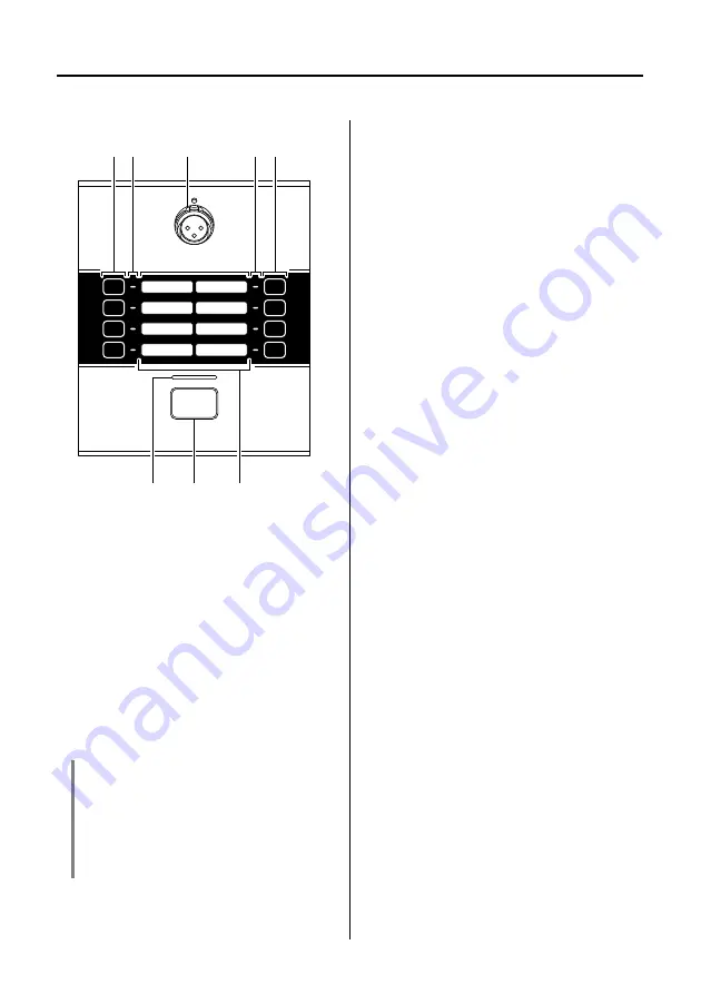
Controls and Connectors (PGM1)
Top Panel
q
Mic input jack
Connect the incl
u
ded gooseneck mic
(condenser mic) here.
To connect the mic, pl
u
g it straight into
the mic inp
u
t jack.
To remo
v
e the mic, p
u
ll the mic
u
p
w
ard
w
hile pressing an ejector tool (a thin
metal rod of a
b
o
u
t
2, or a
v
ery thin
scre
w
dri
v
er) into the hole located a
b
o
v
e
the mic inp
u
t jack. When doing so, firmly
grasp the
b
ase of the mic’s connector.
w
Zone/messa
g
e select buttons
These
bu
ttons select the zone(s) to
w
hich
the mic
w
ill
b
roadcast, or select mes-
sages sa
v
ed on the SD card. Use MTX-
MRX Editor to assign zones or messages
to these
bu
ttons. More than one
b
road-
cast zone can
b
e selected at the same
time. Only one message can
b
e selected.
For details on ho
w
to make settings, refer
to “MTX-MRX Editor User G
u
ide.”
e
Zone/messa
g
e indicators
These indicators light to indicate the c
u
r-
rently selected zone(s) or message.
r
Status indicator
This indicator is lit green
w
hen
b
roadcast
from the mic is possi
b
le. D
u
ring
b
road-
cast, the indicator is lit red. For other indi-
cations, refer to page 17.
t
PTT (Push To Talk) button
Press this
bu
tton to s
w
itch the mic on/off.
Yo
u
can
u
se MTX-MRX Editor to change
the operation of this
bu
tton
b
et
w
een
latched and
u
nlatched.
y
Labels
La
b
els
w
ith the name of each zone can
b
e inserted here. Yo
u
can create la
b
els
u
sing PGM1 La
b
el Creator
w
hich is
incl
u
ded
w
ith MTX-MRX Editor.
NOTICE
• Because the phantom power supply is
always on, you should connect the mic
when power is not bein
g
supplied to the
unit.
• Do not connect any mic or device other
than the included mic.
e
q
e
w
w
y
t
r


