


4-1
Chapter
4
INST
ALLING THE TOOL
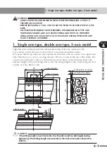
1. Single arm type, double arm type, 2-axis model
w
WARNING
•
ALWAYS TURN THE CONTROLLER POWER OFF BEFORE INSTALLING A TOOL TO
PREVENT AN ACCIDENT.
•
BEFORE INSTALLING A TOOL, CHECK THAT THE ROBOT IS SECURELY FIXED TO THE
BASE.
•
THE USER IS RESPONSIBLE FOR DETERMINING THE REQUIRED BOLT TYPE AND
TIGHTENING TORQUE, AND ACCURATELY INSTALLING THE TOOL. IMPROPER
INSTALLATION CAN CAUSE THE TOOL TO DISLOCATE DURING OPERATION AND
LEAD TO SERIOUS ACCIDENTS.
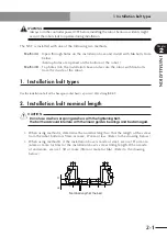
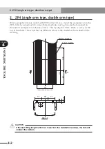
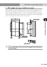
1. Single arm type, double arm type, 2-axis model
Eight M6 coarse thread tap holes and two
φ
6 reamer holes are opened on the
Y-axis slider. Install the user tool onto the Y-axis slider using these holes.
M5 coarse thread tap holes are also opened on the slider side. Use these to fix light loads
other than the tool, such as a wiring retainer. There is a step on the top of the slider. The
actual tool installation surface is the shaded section shown in the drawing. Select the
nominal length of the tool-fixing bolt so that the fitting length of the screw fixing the tool
is 6mm or more, 8mm or less.
70
11
0
(T
olerance between knock (0.02)
90
32
135
8-M6
s
1.0 Depth8
2-
F
6H7 Depth8
6 (Thread insert depth)
90
20
20
8 (Allowable screw depth)
50
19
23.5
4-M5
s
0.8 Depth7
c
CAUTION
If the fi tting length is less than 6mm, the threads could be damaged during
tightening. If the fi tting length exceeds 8mm, the bolt end could contact the
bottom.
Summary of Contents for NXY
Page 2: ......
Page 6: ......
Page 22: ......
Page 26: ...2 4 MEMO ...
Page 28: ......
Page 32: ...3 4 MEMO ...
Page 34: ......
Page 38: ...4 4 MEMO ...
Page 40: ......
Page 48: ......