background image

67

MODX6/MODX7

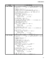
 03 : Panel Switch, LED(スイッチテスト順)

順番

スイッチ名

LED の色

LED 名前

1

ASSIGN 1

RED

ASSIGN 1

2

ASSIGN 2

RED

ASSIGN 2

3

MS HOLD

RED

MS HOLD

4

ARP ON/OFF

ORANGE ARP ON/OFF

5

MS ON/OFF

ORANGE MS ON/OFF

6

MS TRIGGER

RED

MS TRIGGER

7

OCTAVE (TRANSPOSE) –

ORANGE OCTAVE (TRANSPOSE) –

8

OCTAVE (TRANSPOSE) +

ORANGE OCTAVE (TRANSPOSE) +

9

AD INPUT ON/OFF

ORANGE AD INPUT ON/OFF

10

KNOB FUNCTION

ORANGE KNOB FUNCTION

11

KNOB FUNCTION

GREEN

TONE

12

KNOB FUNCTION

GREEN

EQ

13

KNOB FUNCTION

GREEN

ARP

14

KNOB FUNCTION

GREEN

MS

15

ASSIGN

ORANGE ASSIGN

16

PART/ELEMENT

GREEN

PART

17

PART/ELEMENT

GREEN

ELEMENT

18

PART/ELEMENT 1-4/5-8

GREEN

PART 1-4

19

PART/ELEMENT 1-4/5-8

GREEN

PART 5-8

20

SCENE1-4/5-8

GREEN

SCENE 1-4

21

SCENE1-4/5-8

GREEN

SCENE 5-8

22

SCENE 1/5

RED

SCENE 1/5

23

SCENE 2/6

RED

SCENE 2/6

24

SCENE 3/7

RED

SCENE 3/7

25

SCENE 4/8

RED

SCENE 4/8

26

KNOB POSITION 1

-

-

27

KNOB POSITION 2

-

-

28

TOP

-

-

29

<<

-

-

30

>>

-

-

31

REC

RED

REC

32

STOP

-

-

33

PLAY

GREEN

PLAY

34

RHYTHM PATTERN

ORANGE RHYTHM PATTERN

35

CONTROL ASSIGN

ORANGE CONTROL ASSIGN

36

DEC/NO

-

-

37

INC/YES

-

-

38

UP

-

-

39

LEFT

-

-

40

RIGHT

-

-

41

DOWN

-

-

42

EXIT

-

-

43

ENTER

-

-

44

PERFORMANCE (HOME) INFO ORANGE PERFORMANCE (HOME) INFO

45

LIVE SET

ORANGE LIVE SET

46

CATEGORY SEARCH

ORANGE CATEGORY SEARCH

47

UTILITY

ORANGE UTILITY

48

EDIT

ORANGE EDIT

49

PART SELECT

ORANGE PART SELECT

50

STORE

ORANGE STORE

順番

スイッチ名

LED の色

LED 名前

51

AUDITION

ORANGE AUDITION

52

SHIFT

ORANGE SHIFT

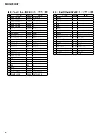
 32 : Panel L2 Check (SW,LED)

(スイッチテスト順)

順番

スイッチ名

LED の色

LED 名前

1

ASSIGN 1

RED

ASSIGN 1

2

ASSIGN 2

RED

ASSIGN 2

3

MS HOLD

RED

MS HOLD

4

ARP ON/OFF

ORANGE ARP ON/OFF

5

MS ON/OFF

ORANGE MS ON/OFF

6

MS TRIGGER

RED

MS TRIGGER

7

OCTAVE (TRANSPOSE) –

ORANGE OCTAVE (TRANSPOSE) –

8

OCTAVE (TRANSPOSE) +

ORANGE OCTAVE (TRANSPOSE) +

Summary of Contents for MODX6

Page 1: ...5 CIRCUIT BOARD LAYOUT 8 DISASSEMBLY PROCEDURE 10 CIRCUIT BOARDS 20 TEST PROGRAM 36 53 INITIAL SETTING 69 FIRMWARE UPDATING PROCEDURES 70 72 SYSTEM BOOTING FLOWCHART 74 CONTENTS DM CIRCUIT BOARD CHEC...

Page 2: ...ha are continually striving to improve Yamaha products Modifications are therefore inevitable and changes in specification are subject to change without notice or obligation to retrofit Should any dis...

Page 3: ...ding type Real time replace Real time overdub Real time punch in out Sequence Format MODX original format SMF formats 0 1 Arpeggio Part 8 Parts simultaneous max Preset 10 239 types User 256 types Moti...

Page 4: ...2nd EQ 2 130 000 480 BPM 5 300 128 16 MODX SMF 0 1 8 10 239 256 8 1 256 2 048 A D USB 4 4 7 VGA TFT LCD USB TO DEVICE USB TO HOST MIDI IN OUT FOOT CONTROLLER 1 2 FOOT SWITCH ASSIGNABLE SUSTAIN OUTPUT...

Page 5: ...button 7 Knobs 1 4 5 8 8 Slider Function PART ELEMENT OPERATOR button 9 Slider Select 1 4 5 8 button 0 Control Sliders 1 4 5 8 9 12 13 16 1 Scene Select 1 4 5 8 button 2 SCENE 1 5 2 6 3 7 4 8 buttons...

Page 6: ...utton 2 Cursor buttons 3 EXIT button 4 ENTER button 5 PERFORMANCE HOME button 6 UTILITY button 7 EDIT button 8 STORE button 9 SHIFT button 0 LIVE SET button 1 CATEGORY button 2 PART SELECT MUTE SOLO b...

Page 7: ...OOT SWITCH ASSIGNABLE SUSTAIN jacks t FOOT CONTROLLER 1 2 jacks y OUTPUT L MONO and R jacks u PHONES Headphone jack i A D INPUT L MONO R jacks o Standby On switch 0 DC IN n q USB TO HOST w USB TO DEVI...

Page 8: ...MODX6 SIDE PAD L L SIDE PAD R R TOME1 TOME1 TPBZ WHEEL ASSEMBLY Ass y PNL2 PNL1 UPPER CASE ASSEMBLY Ass y PNR PNC TOME1 TOME2 TOME3 TOME1 DCIN JK DM KEY IF LOWER CASE ASSEMBLY Ass y KEYBOARD ASSEMBLY...

Page 9: ...1 TOME1 TPBZ WHEEL ASSEMBLY Ass y PNL2 PNL1 UPPER CASE ASSEMBLY Ass y PNR PNC SIDE PAD L L SIDE PAD R R 76L 76H TOME1 TOME2 TOME3 TOME1 DCIN JK DM KEY IF LOWER CASE ASSEMBLY Ass y KEYBOARD ASSEMBLY As...

Page 10: ...X6 Disassembling the Keyboard Assembly 16 8 MODX7 Disassembling the Keyboard Assembly 18 1 Ass y Ass y 10 2 12 3 13 4 PNR 14 5 PNC 14 6 15 7 MODX6 Ass y 16 8 MODX7 Ass y 18 Front side Back side 1 Uppe...

Page 11: ...ODX6 MODX6 O P E N UPPER CASE ASSEMBLY Ass y LOWER CASE ASSEMBLY Ass y TOME4 160 S FLEXIBLE FLAT CABLE S LOCK BAR OPEN OPEN S FLEXIBLE FLAT CABLE S This figure shows the MODX6 MODX6 SUPPORTING MATERIA...

Page 12: ...emoving its fixing screws as listed below Table 1 Table 1 1 Circuit board and Assembly Ref No QTY Fig DM TOME1 370A 2 3 DM UPPER ANGLE DM 370B 9 3 350A 3 3 370C 1 1 JK TOME1 370D 2 3 350B 9 3 PUSH KNO...

Page 13: ...listed below Table 2 3 6 3 1 Ass y 1 3 2 2 Fig 4 4 Table 2 2 Circuit board and Assembly Ref No QTY Fig TPBZ TOME1 570A 2 4 570B 4 4 PNL1 VR KNOB VR 30 1 5 VR KNOB VR 40 2 5 550A 4 4 PNL2 550B 6 4 WHE...

Page 14: ...four 4 slider knobs marked 60 and the S knob marked 90 Fig 5 5 2 Remove the upper case assembly See procedure 1 5 3 Remove the nineteen 19 screws marked 550G The PNR circuit board can then be removed...

Page 15: ...utes 6 1 Remove the upper case assembly See procedure 1 6 2 Remove the TOME1 circuit board See procedure 3 6 3 Remove the six 6 screws marked 550H The LCD angle can then be removed Fig 7 6 4 Remove th...

Page 16: ...f the black keys upward and lift the white and black keys while pulling them toward you a little Fig 10 7 2 5 To remove the white key C6 unhook as described in Procedure 11 2 4 and pull out toward you...

Page 17: ...ONE OCTAVE 1 C3 B3 ONE OCTAVE 1 C4 B4 ONE OCTAVE 1 C5 B5 C6 KEY C6 C1 B1 C2 B2 C3 B3 C4 B4 C5 C6 B5 C1 B1 C2 B2 C3 B3 C4 B4 C5 C6 B5 120B x 4 120B x 4 120B x 3 120B x 3 KEYBOARD ANGLE KEYBOARD ANGLE...

Page 18: ...12 8 3 2 Remove the rubber contacts Fig 12 8 4 76L Circuit Board 8 4 1 Remove the white and black keys from E0 to B3 See Fig 12 and Procedure 8 2 8 4 2 Remove the eleven 11 screws marked 200A The 76L...

Page 19: ...C5 B5 C1 B0 B0 E0 B1 C2 B2 C3 B3 C4 B4 C5 C6 G6 E0 G6 B5 C1 B1 C2 B2 C3 B3 C4 B4 C5 C6 B5 240B x 4 240B x 4 240B x 3 240B x 3 240B x 3 240B x 3 KEYBOARD ANGLE KEYBOARD ANGLE 240A x 2 240B x 2 240A x 2...

Page 20: ...3 JK Circuit Board YJ417D0 21 KEY IF Circuit Board YJ417D0 26 PNC Circuit Board YJ383C0 24 25 PNL1 Circuit Board YJ383C0 26 PNL2 Circuit Board YJ383C0 27 PNR Circuit Board YJ383C0 28 29 TOME1 Circuit...

Page 21: ...21 MODX6 MODX7 JK Circuit Board Component side to DM CB605 to PNC CB100 A A to DM CB205 to DM CB206 CB605 A A to DCIN CB701 to PNL1 CB109 to PNL1 CB110 2NA ZX99470 1...

Page 22: ...MODX6 MODX7 22 DM Circuit Board Component side B B to JK CB104 to KEY IF CB501 B B to JK CB103 to LCD to TPBZ CB601 to JK CB102 2NA ZW84620 1...

Page 23: ...23 MODX6 MODX7 C C Pattern side DM Circuit Board C C 2NA ZW84620 1...

Page 24: ...MODX6 MODX7 24 PNC Circuit Board Component side 2NA ZX42110...

Page 25: ...25 MODX6 MODX7 Pattern side PNC Circuit Board to JK CB401 to PNL1 CB108 to PNL2 CB111 to PB MW to KEY IF CB502 to PNR CB112 2NA ZX42110...

Page 26: ...d Component side to PNC CB102 to JK CB201 to JK CB301 MODX6 to 61H CN1 MODX7 to 76L CN4 MODX6 to 61L CN5 MODX7 N C MODX6 to 61H CN2 MODX7 N C to DM CB504 to PNC CB104 MODX6 N C MODX7 to 76L CN5 MODX6...

Page 27: ...27 MODX6 MODX7 PNL2 Circuit Board to PNC CB103 Component side Pattern side TPBZ Circuit Board Component side to DM CB101 to LCD PNL2 2NA ZX42110 TPBZ 2NA ZX99490 MODX6 2NA ZX99480 MODX7...

Page 28: ...MODX6 MODX7 28 PNR Circuit Board Component side 2NA ZX42110...

Page 29: ...29 MODX6 MODX7 to PNC CB107 Pattern side PNR Circuit Board 2NA ZX42110...

Page 30: ...30 DCIN Circuit Board Component side TOME1 Circuit Board TOME2 Circuit Board TOME3 Circuit Board Component side Component side Component side to JK CB101 DCIN TOME1 TOME2 TOME3 2NA ZX99490 MODX6 2NA Z...

Page 31: ...31 MODX6 MODX7 TOME4 Circuit Board Component side Pattern side 2NA ZX42110...

Page 32: ...MODX6 MODX7 32 2NAK8 V869520 1 61L Circuit Board Component side D D D D to 61H CN3 to KEY IF CB504...

Page 33: ...33 MODX6 MODX7 2NAK8 V869540 61H Circuit Board Component side E E to KEY IF CB505 to KEY IF CB503 to 61L CN4 E E to KEY IF CB505 CN4...

Page 34: ...MODX6 MODX7 34 76L Circuit Board to KEY IF CB503 to KEY IF CB507 to 76H CN2 F F F F Component side 2NAK8 ZW58970...

Page 35: ...35 MODX6 MODX7 76H Circuit Board 2NAK8 ZW58960 Component side to KEY IF CB508 to 76L CN3 G G G G H H H H...

Page 36: ...st jig Following jigs are required for testing Speaker with amplifier MIDI cable USB cable A B type USB flash drive Foot pedal FC3A FC4A or FC5 Foot controller FC7 Monaural plug 150 ohms load Noise le...

Page 37: ...reen never turn off the power Should the power be turned off the WAVE ROM data will be damaged WAVE ROM NG will be shown and no operation will be available Precaution when turning on the power Whether...

Page 38: ...heck MODX 2 3 Selection execution of Test items 1 Select a test item with the INC YES forward buttons or DEC NO backward button The first item No 01 can be jumped to the last item No 35 with the DEC N...

Page 39: ...ound is produced 3 Release the button and the display changes to Press xxx LED xxx button name to be pressed next 4 Check buttons on the panel one after another in the specified order For the order to...

Page 40: ...reased from the current position as shown below And not only the Knob LED but also 3 color LED turns on and off while changing the colors according to increased value SuperKnob Red LED SuperKnob 3 col...

Page 41: ...ch Bend NG is shown While NG is on the display even if the Pitch Bend wheel is moved NG remains displayed 3 Move the Pitch Bend wheel to the upper maximum position 127 according to the display of the...

Page 42: ...n 101 to 127 of the current value is detected OK is shown on the LCD FootSw 11 The target value of 127 is shown on the LCD 12 Depress the pedal of the foot switch FC4A FC5 When 101 to 127 of the curre...

Page 43: ...screen 5 Disconnect the USB cable 13 OUTPUT L 12dB Checks each output level and pitch from the L channel of the jacks 1 Connect the frequency counter to the PHONES jack at L 2 Connect the level meter...

Page 44: ...el input OFF is shown on the LCD 4 Insert the monaural plug for residual noise measurement 150 ohms resistor end to the A D IN PUT R jacks 5 Connect an oscillator to the A D INPUT L MONO jack ON is sh...

Page 45: ...the ENTER button to produce the sine wave sound OFF is shown on the LCD 4 Press the ENTER button to activate the MUTE circuit ON is shown on the LCD and all the output from the PHONES and OUTPUT jack...

Page 46: ...D and a 441Hz sine wave sound is produced Audio 1 test 2 Press the ENTER button and Audio 2 ON is shown on the LCD and a 441Hz sine wave sound is produced Audio 2 test 3 Press the ENTER button and Aud...

Page 47: ...n to shift the display to the EXIT test selection screen 26 Exit Exit the test mode and the power turns off 1 Press the ENTER button and NO or YES is shown on the LCD 2 Press the INC YES button and th...

Page 48: ...ecks whether switches and LEDs on the PNL1 circuit board work properly or not 1 Press the ENTER button and Press AD INPUT ON OFF LED ORANGE is shown on the LCD 2 Press the applicable button and a sine...

Page 49: ...properly or not 1 Press the ENTER button and Press DEC NO LED is shown on the LCD 2 Press the applicable button and a sine wave sound is produced while the button is pressed If the button has LED it...

Page 50: ...m if the following conditions are satisfied PHONES 33 ohms load PHONES L 500 mVp p or less PHONES R 500 mVp p or less OUTPUT 10k ohms load L MONO 400 mVp p or less R 400 mVp p or less Noise Level Chec...

Page 51: ...NE 1 5 23 SCENE 2 6 RED SCENE 2 6 24 SCENE 3 7 RED SCENE 3 7 25 SCENE 4 8 RED SCENE 4 8 26 KNOB POSITION 1 27 KNOB POSITION 2 28 TOP 29 30 31 REC RED REC 32 STOP 33 PLAY GREEN PLAY 34 RHYTHM PATTERN O...

Page 52: ...E 1 5 14 SCENE 2 6 RED SCENE 2 6 15 SCENE 3 7 RED SCENE 3 7 16 SCENE 4 8 RED SCENE 4 8 17 KNOB POSITION 1 18 KNOB POSITION 2 19 TOP 20 21 22 REC RED REC 23 STOP 24 PLAY GREEN PLAY 25 RHYTHM PATTERN OR...

Page 53: ...I USB A B USB FC3A FC4A FC5 FC7 150 A D INPUT 1 5 PHONES PHONES L R ch 33 OUTPUT L MONO R L MONO Rch 10k A D INPUT L MONO R 1 6 MASTER VOLUME Max A D INPUT GAIN Max USB VOLUME MONITOR Max 1 4 Max FOOT...

Page 54: ...7 0 dBu 0 775Vrms 2 2 1 2 1 1 C 2 F2 G 2 C 2 C 2 F2 G 2 C1 C2 C3 2 1 KNOB POSITION 1 CONTROL ASSIGN KNOB POSITION 1 CONTROL ASSIGN Formatting Please keep power on WAVE ROM WAVE ROM NG 2 MODX LCD Super...

Page 55: ...NTER Test Start STORE Factory Set EXIT Exit X XX XX XXXXXX XX X ENTER STORE Factory Set EXIT Exit 2 ENTER Test TEST Program Press ENTER 01 EBUS ID Check MODX 2 3 1 INC YES DEC NO NO 01 DEC NO NO 35 NO...

Page 56: ...2 ENTER LED LCD Single color LED Multi color LED LCD 1 2 3 4 3 LED LCD LCD 4 EXIT 03 Panel Switch LED LED 1 ENTER LCD Press ASSIGN 1 LED RED 2 LED LED NG 3 Press LED 4 67 LED LED KNOB FUNCTION 5 PART...

Page 57: ...0 8 AsgnKnob 1 4 SuperKnob LCD 255 0 255 SuperKnob Knob LED 3 LED SuperKnob LED SuperKnob 3 LED 0 13 1 0 85 14 25 2 86 169 26 38 3 170 251 39 50 4 252 255 51 63 5 64 75 6 76 88 7 89 100 8 101 113 9 1...

Page 58: ...27 0 4 Slider LCD 0 126 0 5 0 1 OK 6 Slider OK EXIT 07 PB MW 1 ENTER LCD 127 Pitch Bend 2 LCD 127 64 Center Pitch Bend NG NG 3 LCD 127 64 127 4 121 127 0 C3 5 LCD 0 127 0 6 0 6 64 G3 7 LCD Center 64 0...

Page 59: ...C1 Foot Controller 1 FC2 Foot Controller 2 5 LCD 0 6 FC7 LCD 0 7 0 3 127 8 LCD 127 9 126 127 OK SustainSw 10 LCD Input FC3 11 FC3A FOOT SWITCH SUSTAIN 12 35 13 14 0 35 101 15 16 101 127 OK FootSw 17 L...

Page 60: ...2 3 MASTER VOLUME 4 ENTER LCD ON 1 kHz 5 1 kHz 0 2 Hz 6 PHONES 33 PHONES L 3 8 2 dBu PHONES R 62 0 dBu OUTPUT 10k L MONO 1 6 2 dBu R 72 0 dBu OUTPUT 10k L MONO 4 1 2 dBu R 7 MASTER VOLUME 8 OUTPUT 10...

Page 61: ...PUT R 13 1kHz 36 dBu 14 A D INPUT GAIN 15 OUTPUT 10k L MONO 62 0 dBu R 1 6 2 dBu 16 A D INPUT GAIN 17 A D INPUT L MONO R 150 18 A D INPUT GAIN 19 OUTPUT 10k L MONO 64 0 dBu R 64 0 dBu 20 EXIT 16 A D D...

Page 62: ...7 EXIT 18 MUTE DAC DAC MUTE 1 2 MASTER VOLUME 3 ENTER L R LCD OFF 4 ENTER DAC MUTE LCD ON 5 ENTER DAC MUTE LCD OFF 6 MUTE ON OUTPUT 10k L MONO 80 0 dBu R 80 0 dBu 7 EXIT 19 ROM eMMC IC403 SUB CPU ROM...

Page 63: ...2 3 ENTER LCD Audio 3 ON 441 Hz Audio 3 4 ENTER LCD Audio 4 ON 441 Hz Audio 4 5 ENTER LCD OK 22 Touch Panel Calibration 1 ENTER LCD 2 3 4 OK 23 TG Interrupt SWP70 CPU 1 ENTER LCD OK OK NG NG 2 LCD OK...

Page 64: ...3 ENTER LCD ON 1 kHz 4 OUTPUT 10k L MONO 8 0 2 dBu 5 EXIT 28 OUTPUT R 0dB R 1 2 MASTER VOLUME 3 ENTER LCD ON 1 kHz 4 OUTPUT 10k R 8 0 2 dBu 5 EXIT 29 OUTPUT L 6dB L 1 2 MASTER VOLUME 3 ENTER LCD ON 1...

Page 65: ...ss ASSIGN 1 LED RED 2 LED LED NG 3 Press LED 4 67 5 OK 6 OK 33 Panel C Check SW LED PNC SW LED 1 ENTER LCD Press KNOB FUNCTION LED ORANGE 2 LED LED NG 3 Press LED 4 68 LED LED 5 OK 6 OK 34 Panel R Che...

Page 66: ...F 1 L R 2 MASTER VOLUME 3 STANDBY ON PHONES 33 PHONES L 500 mVp p PHONES R 500 mVp p OUTPUT 10k L MONO 400 mVp p R 400 mVp p Noise Level 1 L R 2 MASTER VOLUME 3 PHONES 33 PHONES L 80 dBu PHONES R 80 d...

Page 67: ...E 1 5 RED SCENE 1 5 23 SCENE 2 6 RED SCENE 2 6 24 SCENE 3 7 RED SCENE 3 7 25 SCENE 4 8 RED SCENE 4 8 26 KNOB POSITION 1 27 KNOB POSITION 2 28 TOP 29 30 31 REC RED REC 32 STOP 33 PLAY GREEN PLAY 34 RHY...

Page 68: ...E 1 5 14 SCENE 2 6 RED SCENE 2 6 15 SCENE 3 7 RED SCENE 3 7 16 SCENE 4 8 RED SCENE 4 8 17 KNOB POSITION 1 18 KNOB POSITION 2 19 TOP 20 21 22 REC RED REC 23 STOP 24 PLAY GREEN PLAY 25 RHYTHM PATTERN OR...

Page 69: ...69 MODX6 MODX7 INITIAL SETTING STANDBY ON SW off MASTER VOLUME Min A D INPUT GAIN Min USB MONITOR LEVEL Min SLIDER 1 4 Min Pitch Bend Wheel Center Modulation Wheel Min...

Page 70: ...se damage to the boot program 5 If installation failed the Press INC YES to retry message appears on the screen Press INC YES button to retry the installation 6 When an error occurred while installing...

Page 71: ...completed the Super Knob flickers in blue Also Finish Please turn off appears on the screen 5 Turn off the power and remove the USB flash drive 6 Start the Test program and then confirm the firmware v...

Page 72: ...MODX6 MODX7 72 1 2 3 USB 4 5 Press INC YES to retry INC YES 6 DM 8Q86OS_ PGM USB 1 USB TO DVICE USB USB 2 UTILITY UP STANDBY ON UP UTILITY...

Page 73: ...73 MODX6 MODX7 3 Searching for the updater 4 Searching for the updater OK 5 Finish Please turn off 6 USB 7 8 22...

Page 74: ...MODX6 MODX7 74 SYSTEM BOOTING FLOWCHART...

Page 75: ...Judgment criteria Measured GND Measured by Parts with possible defect 5D 5 V power for digital circuit 5 0V 0 5V DGND Multimeter IC010 3 3D 3 3 V power for digital circuit 3 3V 0 3V DGND Multimeter I...

Page 76: ...5D 5V 5 0V 0 5V DGND IC010 3 3D 3 3V 3 3V 0 3V DGND IC009 1 5P 1 5V 1 5V 0 2V DGND IC507 1 0M 1 0V 1 0V 0 2V DGND IC606 5A 5V 5 0V 0 5V AGND IC903 RES CPU Reset 3 3V 0 5V DGND IC002 IC003 y e w q r t...

Page 77: ...ile name 6 The Text input display appears Input the file name to be stored For detailed instructions on entering a name see Naming inputting characters in Basic Operation and Displays page 21 7 Touch...

Page 78: ...USB MODX USB TO DEVICE 2 UTILITY Contents Store Save 3 Content Type Backup File 4 USB 1 2 USB 3 4 5 Save As New File NOTE 6 7 Done NOTE 5 YES USB USB 1 USB MODX USB TO DEVICE 2 UTILITY Contents Load...

Page 79: ...DEVICE USB TO DEVICE USB TO DEVICE USB NOTE USB USB USB USB USB USB USB URL https jp yamaha com support USB1 1 3 0 NOTE USB TO DEVICE 5V 500mA USB USB USB TO DEVICE USB USB USB USB USB USB USB USB US...

Page 80: ...stem settings you created on the Utility display will be erased Make sure you are not overwriting any important data Be sure to save all important data to your USB flash drive before executing this pr...

Page 81: ...r make space by erasing unwanted data from the USB flash drive Auto power off disabled This message appears before Auto Power Off is disabled Bulk data protected Bulk data cannot be received because o...

Page 82: ...thesizer to activate the change of the input output settings for audio data Please reboot to maintain internal memory Please reboot this synthesizer to restore the internal memory Please stop audio pl...

Page 83: ...vice is write protected This message appears when you have attempted to write to a protected USB flash drive USB device read write error An error occurred while reading or writing to from a USB flash...

Page 84: ...data will be lost USB Are you sure Arpeggio full Assignable Knob Full Audio Rec stopped due to lack of memory space USB USB Auto power off disabled Bulk data protected Can t process Completed Connect...

Page 85: ...n internal memory Please stop audio play rec Please stop sequencer Please wait Recall latest edits Redo last recording Sample is protected Sample is too long Sample memory full Scene stored SCENE Song...

Page 86: ...British model C Canadian model D German model E European model F French model H North European model I Indonesian model J Japanese model K Korean model L South east Asia model M Malaysian model O Chi...

Page 87: ...2 MODX6 MODX7 MODX6 OVERALL ASSEMBLY 10 30 40 50 90 70 80 100 110 200 160 170 180 180 60 UPPER CASE 6 ASSEMBLY See page 6 6 Ass y 20 LOWER CASE 6 ASSEMBLY See page 12 6 Ass y...

Page 88: ...PUSH KNOB BLACK Standby On 90 ZQ400100 S KNOB MILK SMOKE Super Knob 100 ZY234800 EN COVER 110 CUSHION PE 8X30X10 ZZ34610 160 WE878300 BIND HEAD SCREW 3 0X6 MFZN2B3 170 WF491001 BIND HEAD TAPPING SCREW...

Page 89: ...4 MODX6 MODX7 MODX7 OVERALL ASSEMBLY 10 30 40 50 90 70 80 100 110 200 160 170 180 180 60 UPPER CASE 7 ASSEMBLY See page 8 7Ass y 20 LOWER CASE 7 ASSEMBLY See page 12 7Ass y...

Page 90: ...ACK Standby On 90 ZQ400100 S KNOB MILK SMOKE Super Knob 100 ZY234800 EN COVER 110 CUSHION PE 8X30X10 ZZ34610 160 WE878300 BIND HEAD SCREW 3 0X6 MFZN2B3 170 WF491001 BIND HEAD TAPPING SCREW B 3 0X30 MF...

Page 91: ...28 20 550 450 460 570 570 570 240 350 470 380 180 180 370 170 550 10 30 70 80 50 50 x6 50 x19 50 x14 60 x3 60 40 90 x2 550 550 550 110 210 200 550 100 120 130 140 190 300 550 550 550 550 550 320 310...

Page 92: ...80 CUSHION PE 1X17X5 ZY83790 2 190 SHADE CUSHION ZZ53030 200 VAM91100 CIRCUIT BOARD PNL1 210 VAM91200 CIRCUIT BOARD PNL2 220 VAM91000 CIRCUIT BOARD PNC 230 VAM91300 CIRCUIT BOARD PNR 240 VAM96200 CIRC...

Page 93: ...50 50 x6 50 x19 50 x14 60 x3 60 40 90 22 24 24 26 28 20 x2 550 550 550 550 110 210 200 550 100 120 130 140 190 300 550 550 550 450 460 570 570 570 240 350 470 380 180 180 550 550 550 320 370 310 170...

Page 94: ...700 180 CUSHION PE 1X17X5 ZY83790 2 190 SHADE CUSHION ZZ53030 200 VAM91100 CIRCUIT BOARD PNL1 210 VAM91200 CIRCUIT BOARD PNL2 220 VAM91000 CIRCUIT BOARD PNC 230 VAM91300 CIRCUIT BOARD PNR 240 VAM94000...

Page 95: ...50 20 10 16N C61 KEYBOARD See page 14 16N C61 260 250 220 220 290 270 240 230 180 100 110 120 110 100 120 150 150 160 190 130 170 370 370 370 350 350 350 350 350 280 210 350 350 350 350 330 350 350 37...

Page 96: ...V928180R FOOT T1 6 2 160 WW693500 RUBBER FOOT 3 170 CUSHION PE 4X32X18 ZZ34590 180 CUSHION PE 6X56X15 ZZ85940 190 CUSHION PE 1X737X5 VAG9830 210 ZY281200 FRONT RAIL 6 29 220 VAM96400 CIRCUIT BOARD TOM...

Page 97: ...250 220 220 290 270 240 230 180 100 120 110 100 120 110 150 150 160 190 130 170 370 370 370 350 350 350 350 280 210 350 350 350 350 350 350 350 330 350 350 370 370 370 330 350 30 50 80 70 60 10 20 32...

Page 98: ...V928180R FOOT T1 6 2 160 WW693500 RUBBER FOOT 3 170 CUSHION PE 4X32X18 ZZ34590 180 CUSHION PE 6X56X15 ZZ85940 190 CUSHION PE 1X960X5 VAG9850 210 ZY281300 FRONT RAIL 7 220 VAM94300 CIRCUIT BOARD TOME1...

Page 99: ...14 MODX6 MODX7 MODX6 KEYBOARD ASSEMBLY Ass y 120 120 220 100 151 152 100 10 10 30 50 50 60 85 90 80 20 40 40 20...

Page 100: ...47740R RUBBER CONTACT 16N 2M 13K 2M 60 KEYBOARD RUBBER CONTACT M 13K 2M V747741 80 VZ303000 FELT L WHITE 11X827 80 VZ303020 FELT L WHITE 11X827 85 VZ302901 FELT U WHITE 5X836 90 WA525102 CUSHION SHEET...

Page 101: ...16 MODX6 MODX7 MODX7 KEYBOARD ASSEMBLY Ass y 240 110 100 140 200 200 250 151 170 165 160 152 120 120 130 60 90 10 20 90 10 20 30 70 40 80 50 240...

Page 102: ...0 V341360R RUBBER CONTACT 16N 2M OCT 2M 5 120 KEYBOARD RUBBER CONTACT 16N 2M OCT 2M V341361 5 130 V3413702 RUBBER CONTACT 16N 2M 76H 2M 140 V3413802 RUBBER CONTACT 16N 2M 76L 2M 151 ZW589700 CIRCUIT B...

Page 103: ...00 WHEEL TUBE PITCH BEND MODULAT 3 50 EW60011R STOPPER CS RING TYPE 60 VN24540R ROTARY VARIABLE RESISTOR TOKU 10 0K RK16311 2 70 CONNECTOR ASSEMBLY PNC PBMW MODX6 ZX75870 70 CONNECTOR ASSEMBLY PNC PBM...

Page 104: ...IC CAPACITOR 150 00 10 0V CHIP C614 ZX880100 CAPACITOR 47 25V RVW 25V470M 617 ZX880100 CAPACITOR 47 25V RVW 25V470M C707 UF037101 CAPACITOR 10 16V C707 UF437100 CAPACITOR 10 16V C752 UF037101 CAPACITO...

Page 105: ...DIN CONNECTOR JACK 5P YKF51 5066 MIDI OUT JK402 VT20250R DIN CONNECTOR JACK 5P YKF51 5066 MIDI IN JK403 VM57600R PHONE CONNECTOR BLACK JACK YKB21 5074 FOOT CONTROLLER1 JK404 VM57600R PHONE CONNECTOR...

Page 106: ...400 SLIDE VARIABLE RESISTOR B 10K RS30111A9 Control1 VR101 ZN551100 ROTARY VARIABLE RESISTOR B 5 0K RD118124Z04 Assign1 VR102 VH335400 SLIDE VARIABLE RESISTOR B 10K RS30111A9 Control2 VR103 ZN551100 R...

Page 107: ...ITOR CHIP 220 10V D145 ZR832500 LED RED GREEN BLUE ASMB MTB1 ZA3A2 D146 ZR832500 LED RED GREEN BLUE ASMB MTB1 ZA3A2 D147 ZR832500 LED RED GREEN BLUE ASMB MTB1 ZA3A2 D148 ZR832500 LED RED GREEN BLUE AS...

Page 108: ...212 RD15510R CARBON RESISTOR CHIP 100 0 1 4 J TP R213 RD155391 CARBON RESISTOR CHIP 390 0 1 4 J TP R214 RD15518R CARBON RESISTOR CHIP 180 0 1 4 J TP R215 RD15518R CARBON RESISTOR CHIP 180 0 1 4 J TP...

Page 109: ...1SS133 1SS176 TE 5 D067 DIODE 1SS133 1SS176 TE 5 VB94121 152 DIODE 1SS133 1SS176 TE 5 VB94121 ZX938900 LCD DISPLAY TM070RBHG13 ZH884700 ADAPTOR SET PA 150B E E ZH884800 ADAPTOR SET PA 150B B B ZH8851...

Page 110: ...17 PNC 18 PNL1 PNL2 19 PNR 20 61L 61H 21 76L 22 76H 23 CIRCUIT DIAGRAM Note See parts list for details of circuit board conponent parts WARNING Components having special characteristics are marked and...

Page 111: ...circuit diagram Page 17 This indicates the location of the counter inter sheet connector The alphabet indicates horizontal direction and the number indicates vertical direction A 2 A 2 is indicates th...

Page 112: ...3D P_IRQ GPIO Tr Tr Tr Tr x16 SSP2_WAITN USB1_OCN USB1_OCN ADINL_INS ADINR_INS SWPM_WAITN AD 15 0 RDN WRN NAND Flash 8Gbit 1GB 2pcs 3 3D D 7 0 JTAG I F debug only BL_ON OFFN 3 3D 25MHz RC filter 12V C...

Page 113: ...CONNECTOR ASSEMBLY PH PH PH PH DM CB605 JK CB104 PH 16P 260 ZX75780 ZX75780 CONNECTOR ASSEMBLY PH PH PH PH DM CB504 KEY IF CB501 PH 7P 270 ZX75790 ZX75790 CONNECTOR ASSEMBLY PH PH PH PH DM CB205 JK CB...

Page 114: ...O_3 3V FI001 NFE31PT222Z1E9L 1 3 2 FI002 NFE31PT222Z1E9L 1 3 2 FI003 NFE31PT222Z1E9L 1 3 2 FI004 NFE31PT222Z1E9L 1 3 2 FI005 NFE31PT222Z1E9L 1 3 2 FI006 NFE31PT222Z1E9L 1 3 2 FI007 NFE31PT222Z1E9L 1 3...

Page 115: ...F N 001 L6 B E E P O N 001 N4 U S B E N B 003 M10 R278 68 R279 68 R280 68 R281 68 NC R282 68 R283 68 R284 68 R285 68 R 2 8 6 4 7 K n o _ u s e R 2 8 7 1 0 K R 2 8 8 1 0 K R 2 9 0 1 0 K R 2 9 1 1 0 K...

Page 116: ...R404 68 R 4 0 1 1 0 0 R 4 0 2 1 0 0 C401 0 1 10 BJ VDDS_DDR DGND C414 0 1 10 BJ DGND C404 0 1 10 BJ C405 0 1 10 BJ C406 0 1 10 BJ C407 0 1 10 BJ C408 0 1 10 BJ C410 0 1 10 BJ C411 0 1 10 BJ C412 0 1 1...

Page 117: ...SCLK NC E3 BCLK NC E2 WCLK1 NC E1 WCLK0 NC A3 SYI D6 SDO0 NC A5 SDO1 NC B5 SDO2 NC C5 SDO3 NC A4 SDO4 B4 SDO5 NC C4 SDO6 NC B3 SDO7 NC D9 SDI0 A8 SDI1 B8 SDI2 C8 SDI3 D8 SDI4 A7 SDI5 B7 SDI6 C7 SDI7 D...

Page 118: ...B2 A 3 002 L4 004 B7 007 B2 A 4 002 L4 004 B7 007 B2 A 5 002 L3 004 B7 007 B2 A 6 002 L3 004 B7 007 B2 A 7 002 L3 004 B7 007 B2 A 8 002 L3 004 B7 007 B3 A 9 002 L3 004 B7 007 B3 A 10 002 L3 004 B6 007...

Page 119: ...8 DQ4 9 VDDQ 1 0 DQ5 1 1 DQ6 1 2 VSSQ 1 3 DQ7 1 4 VDD 1 5 LDQM 1 6 WE 1 7 CAS 1 8 RAS 1 9 CS 2 0 BS0 2 1 BS1 2 2 A10 AP 2 3 A0 2 4 A1 2 5 A2 2 6 A3 2 7 VDD 2 8 VSS 2 9 A4 3 0 A5 3 1 A6 3 2 A7 3 3 A8 3...

Page 120: ...3 R716 10K no_use AD 13 002 N2 004 B4 005 B6 R717 10K no_use M_KONTRGO 005 B8 A 9 002 L3 004 B7 005 B3 AD 12 002 N2 004 B4 005 B6 M_KONTRGI 005 B8 A 8 002 L3 004 B7 005 B3 DGND AD 11 002 N2 004 B4 005...

Page 121: ...6 0 1 25 C117 0 1 25 C110 0 1 25 C119 0 1 25 CB102 PHI 1 2 3 4 CB101 PHI 1 2 3 4 L101 3 3MH 1 2 3 4 NJM2835DL1 09 T IC101 1 VIN 3 G N D 2 VOUT R 1 0 5 2 7 K R 1 2 0 1 0 0 K D104 1SR154 400_TE 2 SSR21N...

Page 122: ...H R 2 0 9 8 2 0 Q203 ISA1235AC1 T112 9A AGND 9A AGND Q204 INC2002AC1 Z201 Z202 Z203 Z204 Z205 Z206 C201 0 1 25 FG C202 0 1 25 C 2 0 3 0 0 1 B C 2 0 7 0 0 1 B C 2 1 2 0 0 1 B C 2 2 1 0 0 1 B C 2 2 4 0...

Page 123: ...L n o _ u s e C 3 0 7 1 0 0 P S L n o _ u s e D301 KDS4148U RTK P D302 KDS4148U RTK P D303 KDS4148U RTK P D304 KDS4148U RTK P FI301 DSS1NB32A271Q93 1 3 2 FI302 DSS1NB32A271Q93 1 3 2 FI303 DSS1NB32A271...

Page 124: ...K D S 4 1 4 8 U R T K P n o _ u s e D 4 0 2 K D S 4 1 4 8 U R T K P n o _ u s e D 4 0 3 K D S 4 1 4 8 U R T K P n o _ u s e D 4 0 4 K D S 4 1 4 8 U R T K P n o _ u s e D 4 0 5 K D S 4 1 4 8 U R T K P...

Page 125: ...B J R 5 1 1 1 K R 5 0 7 3 3 R 5 0 8 3 3 C 5 1 8 1 0 2 5 D 5 0 1 K D S 4 1 4 8 U R T K P n o _ u s e D 5 0 2 K D S 4 1 4 8 U R T K P n o _ u s e D 5 0 3 K D S 4 1 4 8 U R T K P D 5 0 4 K D S 4 1 4 8 U...

Page 126: ...GND C 6 0 7 0 1 1 0 B J 5D DGND IC601 TC7SH00FU TE85L 2 1 4 IC601 V 5 IC601 V 3 IC603 V 1 4 IC603 V 7 74VHCT14AFT BJ IC603 5 3A 6 3Y 74VHCT14AFT BJ IC603 1 1A 2 1Y 74VHCT14AFT BJ IC603 3 2A 4 2Y 74VHC...

Page 127: ...4 5 R G B R 1 9 9 3 9 0 1 4 W R 2 0 0 3 9 0 1 4 W R 2 0 5 3 9 0 1 4 W R 2 0 6 3 9 0 1 4 W R 2 2 0 3 9 0 1 4 W R 2 2 1 3 9 0 1 4 W R 2 0 1 5 6 0 1 4 W R 2 0 2 5 6 0 1 4 W R 2 1 6 5 6 0 1 4 W R 2 1 7 5...

Page 128: ...FG3 FG3 AVSS FG3 Z200 JC1 5 CB109 XHI 1 2 3 4 5 6 3 3A USB Mo AVSS D 8 L 1 S 1 DGND A D INPUT ON OFF OUTPUT in L OUTPUT out L AGND AGND OUTPUT in R OUTPUT out R AGND AGND A D INPUT GAIN in L A D INPU...

Page 129: ...DGND AUDITION D 7 EDIT D 0 Down Encoder D_re STORE D 1 INC YES D 8 L 0 SHIFT D 2 Right L 1 LIVE SET D 3 ENTER DEC NO PNR S 0 CATEGORY D 4 PERFORMANCE Left S 1 PART SELECT D 5 EXIT S 6 ASSIGN SHIFT LI...

Page 130: ...age 16 L 1 to KEY IF CB505 Page 16 J 4 to KEY IF CB504 Page 16 J 3 C4 C6 61H 28CC1 2001136720 C1 B3 61L 28CC1 2001136719 L K J I H G F E D C B A 1 2 3 4 5 6 7 8 1 2 3 4 5 6 7 8 61L 61H CIRCUIT DIAGRM...

Page 131: ...8 1SS133 176 D51 1SS133 176 D3 1SS133 176 D10 1SS133 176 SW23 A 2M 1M SW24 A 2M 1M SW31 A 2M 1M SW9 A 2M 1M D38 1SS133 176 D49 1SS133 176 D43 1SS133 176 D35 1SS133 176 CN4 52147 1210 1 2 3 4 5 6 7 8 9...

Page 132: ...133 176 D149 1SS133 176 D105 1SS133 176 D82 1SS133 176 D89 1SS133 176 D85 1SS133 176 D119 1SS133 176 SW64 A 2M 1M D86 1SS133 176 D151 1SS133 176 D127 1SS133 176 SW68 A 2M 1M SW63 A 2M 1M SW51 A 2M 1M...

Reviews: