42
MODX6/MODX7
LCD display
Test items and judging conditions
08 : FC1/2, Sus/FS
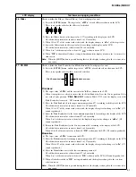
Checks whether [FOOT CONTROLLER 1,2], FOOT SWITCH [ASSIGNABLE] and FOOT SWITCH
[SUSTAIN] jacks work properly or not.
1) Connect the foot controller 1 (FC7) to the [FOOT CONTROLLER 1] and/or the [FOOT CON-
TROLLER 2] jack.
2) Connect the foot switch (FC4A/FC5) to the FOOT SWITCH [ASSIGNABLE] jack.
* Leave the FOOT SWITCH [SUSTAIN] jack unconnected.
3) Press the [ENTER] button.
There is no specific order for these items to be checked.
FC1 (Foot Controller 1), FC2 (Foot Controller 2)
4) The target value “
<0>
” is shown on the LCD.
5) Set the pedal of the foot controller (FC7) to the minimum position (0) (by depressing it toward you
fully) according to the display on the LCD.
When 0 to 3 of the current value is detected, the displayed target value changes to “
<127>
”.
6) Set the pedal to the maximum position (127) (by depressing it away from you fully) according to
the display on the LCD.
When 126 to 127 of the current value is detected, “
OK
” is shown on the LCD.
SustainSw
7) “
Input FC3
” is shown on the LCD.
8) Connect the foot switch (FC3A) to the FOOT SWITCH [SUSTAIN] jack.
When the foot switch (FC3A) is connected, the displayed target value changes to “
<35>
”.
9) Depress the pedal.
When 0 to 35 of the current value is detected, the displayed target value changes to “
<101>
”.
10) Release the pedal.
When 101 to 127 of the current value is detected, “
OK
” is shown on the LCD.
FootSw
11) The target value of “
<127>
” is shown on the LCD.
12) Depress the pedal of the foot switch (FC4A/FC5).
When 101 to 127 of the current value is detected, the displayed target value changes to “
<0>
”.
13) Release the pedal.
When 0 to 35 of the current value is detected, “
OK
” is shown on the LCD. Also “
Extract Plug!
”
is shown.
14) Disconnect the foot switch (FC4A/FC5) from the FOOT SWITCH [ASSIGNABLE] jack.
When the foot switch is disconnected, “
OK
” is shown on the LCD.
15) When all tests resulted in “
OK
”, testing is finished and the display is changed to the test item
selection screen.
Note:
When the [EXIT] button is pressed during this test, the display is changed to the test item selec-
tion screen.
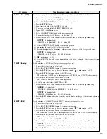
09 : Buzzer
Checks whether the built-in buzzer works properly or not.
1) Press the [ENTER] button, and the built-in buzzer sounds and “ON” is shown on the LCD.
2) It continues to sound at regular intervals until the test is finished.
3) Press the [EXIT] button, and testing is finished and the display is changed to the test item
selection screen.
10 : MIDI
Checks whether the MIDI terminals work properly or not.
1) Connect the MIDI IN and OUT terminals by using a MIDI cable.
2) Press the [
ENTER
] button to start the test.
If no problem is found:
OK
If any problem is found:
NG
3) Confirm that “
OK
” is shown on the LCD.
4) When OK/NG of the test result is shown, testing is finished and the display is changed to the test
item selection screen.
5) Disconnect the MIDI cable from the terminals.
Summary of Contents for MODX6
Page 23: ...23 MODX6 MODX7 C C Pattern side DM Circuit Board C C 2NA ZW84620 1...
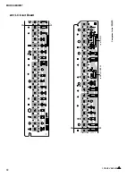
Page 24: ...MODX6 MODX7 24 PNC Circuit Board Component side 2NA ZX42110...
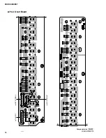
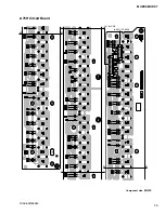
Page 28: ...MODX6 MODX7 28 PNR Circuit Board Component side 2NA ZX42110...
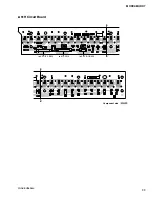
Page 29: ...29 MODX6 MODX7 to PNC CB107 Pattern side PNR Circuit Board 2NA ZX42110...
Page 31: ...31 MODX6 MODX7 TOME4 Circuit Board Component side Pattern side 2NA ZX42110...


