Yamaha mix EMX 2000 Owner'S Manual Download Page 7


6


EMX2000—Owner’s Manual


Master control section


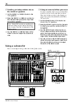
In this section, you can adjust the final level of 
the outputs.


E


MONI 1 (monitor 1) fader


The MONI 1 fader adjusts the final level of the 
signal sent from the MONITOR 1 bus to the 
MONI 1 jack (input/output panel 


9


). If the 

Power amp select switch 


V


 is set to MONI 1-

MONO, using this fader enables you to adjust the 
level of the signal sent from the SPEAKER L 1/2 
jacks to the speakers.


F


MONI 2 (monitor 2) fader


The MONI 2 fader adjusts the final level of the 
signal output from the MONITOR 2 bus to the 
MONI 2 jack (input/output panel 


9


).


G


EFFECT fader


The EFFECT fader adjusts the final level of the 
signal output from the EFFECT bus to the 
EFFECT jack (input/output panel 


A


).


H


ST 1 (stereo 1) fader


The ST 1 fader adjusts the final level of the signal 
sent from the STEREO bus to the ST 1 jacks 
(input/output panel 


8


). If the Power amp select 

switch 


V


 is set to ST L-ST R, this fader also 

adjusts the level of the signal sent to the SPEAK-
ERS jacks (rear panel 


1


).


I


MONO (monaural) fader


The MONO fader adjusts the final level of the 
monaural signal output from the STEREO bus to 
the MONO jack (input/output panel 


0


).

If the Power amp select switch 


V


 is set to 

MONI 1-MONO, this fader also adjusts the level 
of the signal sent from the SPEAKERS R 1/2 jacks 
to the speakers.

If the Power amp select switch 


V


 is set to MONO 

BRIDGE, this fader adjusts the level of the signal 
sent from the SPEAKERS BRIDGE jack to the 
speaker.


J


AFL (after fader listen)


When this switch is on, the output signal that 
passes through the corresponding fader is sent to 
the PHONES/C-R OUT jack (input/output panel 


B


). Use these switches when you wish to moni-

tor a particular output signal through the head-
phones.


Tape in section


In this section, you can adjust the input level of a 
cassette deck or a CD player that is connected to 
the TAPE jacks (input/output panel 


5


).


K


ST (stereo) control


This knob adjusts the level of the signal sent from 
the TAPE jacks to the STEREO bus.


L


PFL (pre-fader listen) switch

When this switch is on, the signal input from the 
TAPE jacks is routed at the point before the ST 
control to the PHONES/C-R OUT jack (input/
output panel 

B

).

Note:   The setting of this fader does not affect 
the level of the signal sent from the EFFECT 
bus to the built-in effect.

Note:   The setting of this fader does not affect 
the signal output from the STEREO bus to the 
ST 2 jacks.

AFL

AFL

AFL

AFL

AFL

0

5

10

15

20

25

30
40
50

0

5

10

15

20

25

30
40
50

0

5

10

15

20

25

30
40
50

0

5

10

15

20

25

30
40
50

0

5

10

15

20

25

30
40
50

MONI 1

MONO

ST 1

EFFECT

MONI 2

E

F

G

H

I

J

TAPE IN

10

0

ST

PFL

K

L

Summary of Contents for mix EMX 2000

Page 1: ...6 5 PFL 10 0 MONI 1 10 0 MONI 2 EFFECT PAN 10 0 R L 15 15 HIGH 15 15 MID 15 15 LOW 34 10 GAIN 60 16 4 PFL 10 0 MONI 1 10 0 MONI 2 EFFECT PAN 10 0 R L 15 15 HIGH 15 15 MID 15 15 LOW 34 10 GAIN 60 16 3...

Page 2: ...ne of the following measures Relocate either this product or the device that is being affected by the interference Utilize power outlets that are on different branch circuit breaker or fuse circuits o...

Page 3: ...wo speakers to each speaker output jack Monaural main bridge connection The two channel power amp is bridge con nected and the main monaural mix signal is out put from BRIDGE jack You can connect only...

Page 4: ...e internal circuitry voids the warranty 5 Always power off before making connec tions Always turn the power OFF before connecting or disconnecting cables This is important to pre vent damage to the un...

Page 5: ...is flat when the knobs are in the position Rotating it toward the right will boost the corresponding frequency band and rotating it toward the left will cut it The base frequency or center frequency...

Page 6: ...ed to the ST SUB 1 2 jacks on the input output panel A MONI 1 monitor 1 control The MONI 1 knob adjusts the amount of the sig nal sent from the ST SUB 1 and 2 jacks input output panel 4 to the MONITOR...

Page 7: ...1 MONO this fader also adjusts the level of the signal sent from the SPEAKERS R 1 2 jacks to the speakers If the Power amp select switch V is set to MONO BRIDGE this fader adjusts the level of the sig...

Page 8: ...acks input output panel 8 and MONO jack input output panel 0 S ON switch This switch turns the graphic equalizer on off Power amp section This section allows you to select the signals that will be inp...

Page 9: ...als is adjusted by the master MONI 1 fader and the MONO fader MONO BRIDGE The monaural signal that is a mix of the STEREO bus is output from the BRIDGE jack The final level of this signal is adjusted...

Page 10: ...al input output levels are 0 dB MONO 4dB FOOT SW MONI MONI MONO PAMP IN 2 EFFECT 4dB PHONES C R OUT 4dB 8 7 6 5 4 3 2 1 A A R ST 1 L R R R ST 2 1 L L REC 10dBV R L TAPE R L L ST SUB 2 MONO L R ST SUB...

Page 11: ...fader control panel F respectively to adjust the final level of the signals output from these jacks The nominal output level is 4 dB 0 MONO monaural jack This phone jack mixes the STEREO bus signals...

Page 12: ...er channel The maximum output is 200W 200W with two 4 speakers If you wish to use two speakers per channel use 8 16 speakers The maximum output is 200W 200W with 8 impedance When the Power amp select...

Page 13: ...m can be connected to the ST 1 2 MONO and MONI 1 2 jacks on the front panel Connecting a single speaker to the BRIDGE jack Connecting one speaker to each of the L R jacks Connecting two speakers to ea...

Page 14: ...ect allow ing reverberation or ambiance to be added to vocals or instrumental sounds 1 Connect a mic or instrument to the desired channels and adjust the volume and tone 2 Press the ON switch of the d...

Page 15: ...REVERB 2 VOCAL REVERB 3 VOCAL REVERB 4 HALL 1 HALL 2 HALL 3 ROOM PLATE 1 PLATE 2 PLATE 3 GATE REVERB 15 15 HIGH PEAK PEAK PEAK 15 15 MID 15 15 LOW 34 10 GAIN 60 16 9 10 PFL 34 10 GAIN 10 0 MONI 1 10...

Page 16: ...PEAK 15 15 MID 15 15 LOW 34 10 GAIN 60 16 9 10 PFL 34 10 GAIN 10 0 MONI 1 10 0 MONI 2 EFFECT BAL 10 0 R L 15 15 HIGH 15 15 MID 15 15 LOW 8 PFL 10 0 MONI 1 10 0 MONI 2 EFFECT PAN 10 0 R L 15 15 HIGH 15...

Page 17: ...RB 2 VOCAL REVERB 3 VOCAL REVERB 4 HALL 1 HALL 2 HALL 3 ROOM PLATE 1 PLATE 2 PLATE 3 GATE REVERB 15 15 HIGH PEAK PEAK PEAK 15 15 MID 15 15 LOW 34 10 GAIN 60 16 9 10 PFL 34 10 GAIN 10 0 MONI 1 10 0 MON...

Page 18: ...trol at maximum 80 dB EFFECT SEND MONITOR OUT Master fader at maximum level and all channel level controls at minimum Maximum voltage gain 91 dB MIC IN to SPEAKER OUT CH 1 8 64 dB MIC IN to ST OUT CH...

Page 19: ...15 5 mV 10 dB 2 45 V 14 dB 155 mV 30 dB 24 5 V PHONE JACK TRS 2 ST INPUT 9 12 MAX MIN 10 k 600 Lines 34 dB 15 5 mV 10 dB 2 45 V 14 dB 155 mV 30 dB 24 5 V PHONE JACK3 ST SUB IN 1 2 10 k 600 Lines 4 dB...

Page 20: ...19 EMX2000 Owner s Manual Dimensions Unit mm 167 6 W 480 D 454 H 125 277 7...

Page 21: ...GRAM FOOT SW DSP EFFECT PEAK A B 10R 12R 9L 11L 10R 12R 9L 11L 11 12 INPUT 9 10 MONO B A L MONO L R ST SUB 1 2 to to from from IN R P AMP ST 1 ON LINE LINE INPUT 5 8 INPUT 1 4 TAPE R EFFECT MONITOR AF...

Page 22: ...YAMAHA CORPORATION VZ42360 R1 1 IP 24 Pro Audio Division 18 3 P O Box 3 Hamamatsu 430 8651 Japan NP Printed in Taiwan...

Reviews: