background image


3


EMX2000—Owner’s Manual


Precautions


1. Avoid excessive heat, humidity, dust and 

vibration


Keep the unit away from locations where it is 
likely to be exposed to high temperatures or 
humidity — such as near radiators, stoves, etc. 
Also avoid locations which are subject to exces-
sive dust accumulation or vibration which could 
cause mechanical damage.


2. Ventilation


Allow a distance of 30 cm between the unit and 
the wall so that heat generated from the unit will 
be released effectively. Also, allow enough space 
between the unit and other devices. If you mount 
the unit in an audio rack, keep a space of 40 cm 
on the top panel, and a space of 15 cm to the side 
panel. Remove the rear panel of the rack or open 
a vent hole. If heat release is inadequate, the unit 
will retain heat inside the unit, which may cause a 
fire.


3. Avoid physical shocks


Strong physical shocks to the unit can cause dam-
age. Handle it with care.


4. Do not open the case or attempt repairs 

or modifications yourself


This product contains no user-serviceable parts. 

Refer all maintenance to qualified Yamaha service 
personnel. Opening the case and/or tampering 
with the internal circuitry voids the warranty.


5. Always power off before making connec-

tions


Always turn the power OFF before connecting or 
disconnecting cables. This is important to pre-
vent damage to the unit itself as well as other con-
nected equipment.


6. Handle cables carefully


Always plug and unplug cables — including the 
AC power cord — by gripping the connector, not 
the cord.


7. Clean with a soft dry cloth


Never use solvents such as benzine or thinner to 
clean the unit. Wipe clean with a soft, dry cloth.


8. Always use the correct power supply


Make sure that the power supply voltage specified 
on the rear panel matches your local AC mains 
supply. Also make sure that the AC mains supply 
can deliver more than enough current to handle 
all equipment used in your system.


9. Do not touch the heatsink when the 

EMX2000 is in use. It can get very hot.


Contents


Front and rear panel................................ 4


Control panel ...................................................4


Input/output panel.................................. 9


Rear panel.......................................................11


Connections........................................... 12


Connecting speakers......................................12
Connecting input/output equipment...........12


Basic operation ...................................... 13


Connecting microphones and instruments .13
Using the digital effect ...................................13


Example setups ...................................... 14


As a band PA ..................................................14
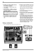
As a conference/entertainment hall sound
system .............................................................15
Using a subwoofer .........................................16


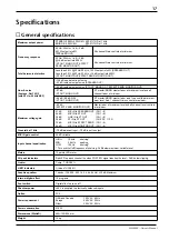
Specifications......................................... 17


General specifications.................................... 17
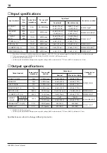
Input specifications ....................................... 18
Output specifications .................................... 18


Dimensions............................................ 19

Block/Level Diagram............................. 20

Summary of Contents for mix EMX 2000

Page 1: ...6 5 PFL 10 0 MONI 1 10 0 MONI 2 EFFECT PAN 10 0 R L 15 15 HIGH 15 15 MID 15 15 LOW 34 10 GAIN 60 16 4 PFL 10 0 MONI 1 10 0 MONI 2 EFFECT PAN 10 0 R L 15 15 HIGH 15 15 MID 15 15 LOW 34 10 GAIN 60 16 3...

Page 2: ...ne of the following measures Relocate either this product or the device that is being affected by the interference Utilize power outlets that are on different branch circuit breaker or fuse circuits o...

Page 3: ...wo speakers to each speaker output jack Monaural main bridge connection The two channel power amp is bridge con nected and the main monaural mix signal is out put from BRIDGE jack You can connect only...

Page 4: ...e internal circuitry voids the warranty 5 Always power off before making connec tions Always turn the power OFF before connecting or disconnecting cables This is important to pre vent damage to the un...

Page 5: ...is flat when the knobs are in the position Rotating it toward the right will boost the corresponding frequency band and rotating it toward the left will cut it The base frequency or center frequency...

Page 6: ...ed to the ST SUB 1 2 jacks on the input output panel A MONI 1 monitor 1 control The MONI 1 knob adjusts the amount of the sig nal sent from the ST SUB 1 and 2 jacks input output panel 4 to the MONITOR...

Page 7: ...1 MONO this fader also adjusts the level of the signal sent from the SPEAKERS R 1 2 jacks to the speakers If the Power amp select switch V is set to MONO BRIDGE this fader adjusts the level of the sig...

Page 8: ...acks input output panel 8 and MONO jack input output panel 0 S ON switch This switch turns the graphic equalizer on off Power amp section This section allows you to select the signals that will be inp...

Page 9: ...als is adjusted by the master MONI 1 fader and the MONO fader MONO BRIDGE The monaural signal that is a mix of the STEREO bus is output from the BRIDGE jack The final level of this signal is adjusted...

Page 10: ...al input output levels are 0 dB MONO 4dB FOOT SW MONI MONI MONO PAMP IN 2 EFFECT 4dB PHONES C R OUT 4dB 8 7 6 5 4 3 2 1 A A R ST 1 L R R R ST 2 1 L L REC 10dBV R L TAPE R L L ST SUB 2 MONO L R ST SUB...

Page 11: ...fader control panel F respectively to adjust the final level of the signals output from these jacks The nominal output level is 4 dB 0 MONO monaural jack This phone jack mixes the STEREO bus signals...

Page 12: ...er channel The maximum output is 200W 200W with two 4 speakers If you wish to use two speakers per channel use 8 16 speakers The maximum output is 200W 200W with 8 impedance When the Power amp select...

Page 13: ...m can be connected to the ST 1 2 MONO and MONI 1 2 jacks on the front panel Connecting a single speaker to the BRIDGE jack Connecting one speaker to each of the L R jacks Connecting two speakers to ea...

Page 14: ...ect allow ing reverberation or ambiance to be added to vocals or instrumental sounds 1 Connect a mic or instrument to the desired channels and adjust the volume and tone 2 Press the ON switch of the d...

Page 15: ...REVERB 2 VOCAL REVERB 3 VOCAL REVERB 4 HALL 1 HALL 2 HALL 3 ROOM PLATE 1 PLATE 2 PLATE 3 GATE REVERB 15 15 HIGH PEAK PEAK PEAK 15 15 MID 15 15 LOW 34 10 GAIN 60 16 9 10 PFL 34 10 GAIN 10 0 MONI 1 10...

Page 16: ...PEAK 15 15 MID 15 15 LOW 34 10 GAIN 60 16 9 10 PFL 34 10 GAIN 10 0 MONI 1 10 0 MONI 2 EFFECT BAL 10 0 R L 15 15 HIGH 15 15 MID 15 15 LOW 8 PFL 10 0 MONI 1 10 0 MONI 2 EFFECT PAN 10 0 R L 15 15 HIGH 15...

Page 17: ...RB 2 VOCAL REVERB 3 VOCAL REVERB 4 HALL 1 HALL 2 HALL 3 ROOM PLATE 1 PLATE 2 PLATE 3 GATE REVERB 15 15 HIGH PEAK PEAK PEAK 15 15 MID 15 15 LOW 34 10 GAIN 60 16 9 10 PFL 34 10 GAIN 10 0 MONI 1 10 0 MON...

Page 18: ...trol at maximum 80 dB EFFECT SEND MONITOR OUT Master fader at maximum level and all channel level controls at minimum Maximum voltage gain 91 dB MIC IN to SPEAKER OUT CH 1 8 64 dB MIC IN to ST OUT CH...

Page 19: ...15 5 mV 10 dB 2 45 V 14 dB 155 mV 30 dB 24 5 V PHONE JACK TRS 2 ST INPUT 9 12 MAX MIN 10 k 600 Lines 34 dB 15 5 mV 10 dB 2 45 V 14 dB 155 mV 30 dB 24 5 V PHONE JACK3 ST SUB IN 1 2 10 k 600 Lines 4 dB...

Page 20: ...19 EMX2000 Owner s Manual Dimensions Unit mm 167 6 W 480 D 454 H 125 277 7...

Page 21: ...GRAM FOOT SW DSP EFFECT PEAK A B 10R 12R 9L 11L 10R 12R 9L 11L 11 12 INPUT 9 10 MONO B A L MONO L R ST SUB 1 2 to to from from IN R P AMP ST 1 ON LINE LINE INPUT 5 8 INPUT 1 4 TAPE R EFFECT MONITOR AF...

Page 22: ...YAMAHA CORPORATION VZ42360 R1 1 IP 24 Pro Audio Division 18 3 P O Box 3 Hamamatsu 430 8651 Japan NP Printed in Taiwan...

Reviews: