18
DRX-730/NX-E700
DRX-730/NX-E70
0
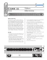
RS232C cross cable
RS232C conversion jig
Reset switch
Flexible flat cable 8P
Writing port
"STANDBY/ON" key
Rear side
Front side
SW301
FLASH
UCOM
OTHER
●
Connection
1. Set the switch (SW301) of RS232C conversion adapter to the “FLASH UCOM” side.
2. Connect the writing port of this unit to the serial port (RS232C) of the PC with RS232C cross cable, RS232C con-
version jig and flexible flat cable as shown below. (Fig. 1)
Fig. 1
●
Operation
Procedures
1. Connect the power cable of this unit to the AC outlet.
2. While pressing the reset switch of RS232C conversion jig, press the “STANDBY/ON” key of this unit to turn on the
power. (Fig. 1)
3. Start up FlashSta.exe, the screen will appear as shown below. (Fig. 2)
Select Internal flash memory
Select the port of RS-232C
Fig. 2
4. Select the port and data to be transmitted. (Fig. 2)
• Select
Program
Select Internal flash memory
• RS232C
Select the port of RS-232C
* For selection of the port, COM1 to 4 can be
used.
As COM5 or higher port cannot be used, se-
lect out of COM 1 to 4 of the setting on the PC
side.
Summary of Contents for MCR-730
Page 71: ...DRX 730 NX E700 ...