background image

11 

En

Connections

English

PRE

P

ARA

T

ION

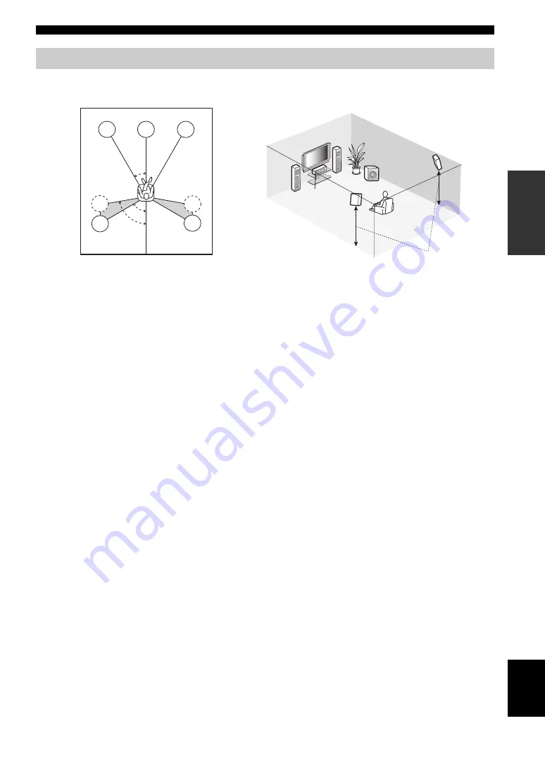
The speaker layout below shows the speaker setting we recommend. You can use it to enjoy CINEMA DSP and multi-
channel audio sources.


Front left and right speakers (FL and FR)

The front speakers are used for the main source sound plus effect sounds. Place these speakers at an equal distance from the 
ideal listening position. The distance of each speaker from each side of the video monitor should be the same.

Center speaker (C)

The center speaker is for the center channel sounds (dialog, vocals, etc.). If for some reason it is not practical to use a 
center speaker, you can do without it. Best results, however, are obtained with the full system. 

Surround left and right speakers (SL and SR)

The surround speakers are used for effect and surround sounds.

Subwoofer (SW)

The use of a subwoofer with a built-in amplifier, such as the Yamaha Active Servo Processing Subwoofer System, is 
effective not only for reinforcing bass frequencies from any or all channels, but also for high fidelity sound reproduction 
of the LFE (low-frequency effect) channel included in Dolby Digital and DTS sources. The position of the subwoofer is 
not so critical, because low bass sounds are not highly directional. But it is better to place the subwoofer near the front 
speakers. Turn it slightly toward the center of the room to reduce wall reflections.

Placing speakers

60˚

30˚

FL

FR

C

SL

SR

SR

80˚

SL

FR

FL

C

SL

SR 

SW

1.8 m (6 ft)

Summary of Contents for HTR-6050

Page 1: ...HTR 6050 AV Receiver OWNER S MANUAL U ...

Page 2: ...f you are not sure of the type of power supply to your home consult your product dealer or local power company For products intended to operate from battery power or other sources refer to the operating instructions 12 Grounding or Polarization This product may be equipped with a polarized alternating current line plug a plug having one blade wider than the other This plug will fit into the power ...

Page 3: ...ntion to Article 820 40 of the NEC that provides guidelines for proper grounding and in particular specifies that the cable ground shall be connected to the grounding system of the building as close to the point of cable entry as practical FCC INFORMATION for US customers 1 IMPORTANT NOTICE DO NOT MODIFY THIS UNIT This product when installed as indicated in the instructions contained in this manua...

Page 4: ...is might damage the finish Use a clean dry cloth 12 Only voltage specified on this unit must be used Using this unit with a higher voltage than specified is dangerous and may cause fire damage to this unit and or personal injury Yamaha will not be held responsible for any damage resulting from use of this unit with a voltage other than specified 13 To prevent damage by lightning keep the power cor...

Page 5: ...42 Using a USB memory device or a USB portable audio player 43 Playback operation 43 Recording 45 SET MENU 46 Using SET MENU 47 1 SOUND MENU 48 2 INPUT MENU 52 3 OPTION MENU 54 Remote control features 56 Using remote control on the SCENE feature 56 Controlling this unit a TV or other components 57 Setting remote control codes 59 Advanced setup 60 Troubleshooting 61 Glossary 68 Specifications 70 In...

Page 6: ...imize this unit to suit your individual audiovisual system Component video input output capability 3 COMPONENT VIDEO INs and 1 MONITOR OUT S video signal input output capability Optical and coaxial digital audio signal jacks Sleep timer Cinema and music night listening modes Remote control with preset remote control codes Manufactured under license from Dolby Laboratories Dolby Pro Logic and the d...

Page 7: ...batteries have leaked dispose of them immediately Avoid touching the leaked material or letting it come into contact with clothing etc Clean the battery compartment thoroughly before installing new batteries Do not throw away batteries with general house waste dispose of them correctly in accordance with your local regulations If the remote control is without batteries for more than 2 minutes or i...

Page 8: ...ack Speaker cables 5 Subwoofer cable 1 Select a monaural RCA cable DVD player 1 Select DVD player equipped with coaxial digital audio output jack and composite video output jack Video monitor 1 Select a TV monitor video monitor or projector equipped with a composite video input jack Video cable 2 Select an RCA composite video cable Digital coaxial audio cable 1 Quick start guide Front right speake...

Page 9: ...tal part of this unit Be sure to connect the left channel L right channel R red and black properly Front speakers Center and surround speakers 4 Connect the subwoofer cable to the input jack of the subwoofer and the SUBWOOFER OUTPUT jack of this unit Step 1 Set up your speakers MULTI CH INPUT COMPONENT VIDEO DIGITAL INPUT VIDEO ANTENNA SPEAKERS L R L R SURROUND CENTER FRONT B AUDIO OUTPUT L 1 2 3 ...

Page 10: ...ENTER FRONT B AUDIO OUTPUT L 1 2 3 R L R L R DVD DTV CBL DVR CD SUB WOOFER IN OUT CENTER SUBWOOFER SURROUND FRONT DVD OPTICAL COAXIAL CD DTV CBL DVD PR PB Y DTV CBL DVR DVD S VIDEO VIDEO DVR AM FRONT A GND FM UNBAL 75 IN OUT DTV CBL MONITOR OUT MONITOR OUT MD CD R OUT REC IN PLAY HDMI DVD OUT DTV CBL AC OUTLETS Make sure that this unit and the DVD player are unplugged from the AC wall outlets Digi...

Page 11: ...th AC OUTLETS for the power supply of the other components See page 21 for details Note Indoor FM antenna AM loop antenna Open the lever Insert Close the lever For further connections Using the other kind of speaker combinations P 12 Connecting a video monitor P 16 Connecting a DVD player P 16 Connecting a DVD recorder P 16 Connecting a cable TV or a satellite tuner P 16 Connecting a CD player and...

Page 12: ...rogram the SCENE mode is deactivated and the indicator on the selected SCENE button turns off Using the other SCENE buttons In the following cases try pressing the corresponding SCENE button to enjoy playback of the desired sources Case A I want to listen to a music disc from the connected DVD player as the back ground music for this room Press FSCENE 2 or ESCENE 2 to select Disc Listening Case B ...

Page 13: ...1STANDBY ON or MPOWER See page 21 for details In the standby mode this unit consumes a small amount of power in order to receive infrared signals from the remote control Notes Note What do you want to do with this unit Customizing the SCENE templates Using various SCENE templates P 28 Creating your original SCENE templates P 31 Using various input sources Basic controls of this unit P 32 Enjoying ...

Page 14: ...ion 8 MULTI CH INPUT jacks See page 19 for connection information 9 AUDIO jacks See pages 16 and 19 for connection information 0 SUBWOOFER OUTPUT jack See page 12 for connection information Connections Rear panel MULTI CH INPUT COMPONENT VIDEO DIGITAL INPUT VIDEO ANTENNA SPEAKERS L R L R SURROUND CENTER FRONT B AUDIO OUTPUT L 1 2 3 R L R L R DVD DTV CBL DVR CD SUB WOOFER IN OUT CENTER SUBWOOFER SU...

Page 15: ...out it Best results however are obtained with the full system Surround left and right speakers SL and SR The surround speakers are used for effect and surround sounds Subwoofer SW The use of a subwoofer with a built in amplifier such as the Yamaha Active Servo Processing Subwoofer System is effective not only for reinforcing bass frequencies from any or all channels but also for high fidelity soun...

Page 16: ...etal part of this unit This could damage this unit and or the speakers Use the magnetically shielded speakers If this type of speaker still creates interference with the monitor place the speakers away from the monitor If you are to use 6 ohm speakers be sure to set SP IMP to 6Ω MIN before using this unit see page 13 Note Subwoofer Center speaker MULTI CH INPUT COMPONENT VIDEO DIGITAL INPUT VIDEO ...

Page 17: ...r widely used to terminate speaker cables First tighten the knob and then insert the banana plug connector into the end of the corresponding terminal 1 Make sure this unit is turned off See page 21 for details about turning on or off this unit 2 Press and hold 0TONE CONTROL and then press 1STANDBY ON to turn on this unit This unit turns on an the advanced setup menu appears in the front panel disp...

Page 18: ...k be sure to put the cap back in place This cap protects the jack from dust Video jacks This unit has three types of video jacks Connection depends on the availability of input jacks on your video monitor VIDEO jacks For conventional composite video signals transmitted via composite video cables S VIDEO jacks For S video signals separated into the luminance Y and chrominance C video signals transm...

Page 19: ... the connected video monitor Refer to the instruction manual of each connected component HDMI jack and cable plug y We recommend using an HDMI cable shorter than 5 meters 16 feet with the HDMI logo printed on it Use a conversion cable HDMI jack DVI D jack to connect this unit to other DVI components Information on HDMI Audio signals input at the HDMI jack are not output from any speaker terminals ...

Page 20: ... DVD OPTICAL COAXIAL CD DTV CBL DVD PR PB Y DTV CBL DVR DVD DVD S VIDEO VIDEO DVR IN OUT DTV CBL MONITOR OUT MONITOR OUT HDMI DVD OUT DTV CBL C L R V V DVD player Video monitor Video in Video out Audio out Audio out indicates recommended connections indicates alternative connections MULTI CH INPUT COMPONENT VIDEO DIGITAL INPUT VIDEO AUDIO L 1 3 R L R DTV CBL DVR CD IN OUT CENTER SUBWOOFER SURROUND...

Page 21: ... video images on the video monitor connected to the HDMI OUT jack Audio video signals output from the connected component such as DVD player etc are output to the connected video monitor only when this unit is turned on and set to the input source DVD or DTV CBL Available audio video signals depend on the specification of the connected video monitor Refer to the instruction manual of each connecte...

Page 22: ... PB Y PR PB Y PR PB Y PR PB Y DVD player Video monitor Video out Video out Video out Video in Cable TV or satellite tuner DVD recorder VIDEO AUDIO L R DTV CBL DVR CD IN OUT DVD DVD S VIDEO VIDEO DVR IN OUT DTV CBL MONITOR OUT HDMI DVD OUT DTV CBL S S S S S DVD player Video monitor Video out Video out Video out Video in Cable TV or satellite tuner DVD recorder Video in ...

Page 23: ...put source see page 33 this unit automatically turns off the digital sound field processor and you cannot select sound field programs This unit does not redirect signals input at the MULTI CH INPUT jacks to accommodate for missing speakers We recommend that you connect a 5 1 channel speaker system before using this feature Connecting audio components Note Make sure that this unit and other compone...

Page 24: ...M antenna is connected to this unit Using the VIDEO AUX jacks on the front panel Caution Be sure to turn down the volume of this unit and other components before making connections Notes SPEAKERS PHONES SILENT CINEMA STANDBY ON A B OFF l PRESET TUNING h A B C D E FM AM EDIT PRESET TUNING MEMORY TUNING AUTO MAN L OPTIMIZER MIC AUDIO SELECT DIRECT STEREO STRAIGHT EFFECT TONE CONTROL l INPUT h l PROG...

Page 25: ...rmation on the maximum power or the total power consumption of the components that can be connected to these outlets see Specifications on page 70 Turning on this unit Press 1STANDBY ON or MPOWER to turn on this unit y When you turn on this unit there will be a 4 to 5 second delay before this unit can reproduce sound Set this unit to the standby mode Press 1STANDBY ON or NSTANDBY to set this unit ...

Page 26: ...tal audio signals A Headphones indicator Lights up when headphones are connected see page 36 B SP A B indicators Light up according to the set of front speakers selected see page 33 C NIGHT indicator Lights up when you select a night listening mode see page 35 D CINEMA DSP indicator Lights up when you select a CINEMA DSP sound field program see page 37 HiFi DSP indicator Lights up when you select ...

Page 27: ...water or other liquids on the remote control Do not drop the remote control Do not leave or store the remote control in the following types of conditions places of high humidity such as near a bath places of high temperature such as near a heater or stove places of extremely low temperatures dusty places Notes SPEAKERS PHONES SILENT CINEMA STANDBY ON A B OFF l PRESET TUNING h A B C D E FM AM EDIT ...

Page 28: ...ely Headphones are disconnected from this unit This unit and the video monitor are turned on The connected subwoofer is turned on and the volume level is set to about half way or slightly less The crossover frequency controls of the connected subwoofer is set to the maximum FRONT A speakers are selected as the front speaker system see page 33 The room is sufficiently quiet 2 Connect the supplied o...

Page 29: ...connected and the polarity of each speaker Also checks and adjusts the volume level of each speaker Speaker distance DISTANCE Checks the distance of each speaker from the listening position and adjusts the timing of each channel Speaker size SIZE Checks the frequency response of each speaker and sets the appropriate low frequency crossover for each channel The display changes as follows The result...

Page 30: ...UP results Select CANCEL to cancel the AUTO SETUP results 10 Press GENTER to confirm your selection The top SET MENU display appears in the OSD 11 Press QMENU to exit from SET MENU 12 Disconnect the optimizer microphone from this unit The optimizer microphone is sensitive to heat Keep it away from direct sunlight and do not place it on top of this unit y If you change speakers speaker positions or...

Page 31: ... do not cancel the AUTO SETUP procedure 1 Make sure the pointer is pointing at WARNING and then press GENTER to display the detailed information about the warning The number on the right of WARNING indicates the number of warning messages 2 Press Gl h repeatedly to toggle between the warning displays y For details about each warning message see the AUTO SETUP section in Troubleshooting on page 65 ...

Page 32: ...te appears in the front panel display 2 Press DINPUT l h or press DAMP and then press Gl h to select the desired template 3 Press the FSCENE or ESCENE button again to confirm the selection The selected SCENE template is assigned to the button If you do not carry out any operation within 30 seconds from the last operation in these steps this procedure is automatically canceled Once the desired SCEN...

Page 33: ...B Audio Listening DVD Live Viewing DVD Movie Viewing DVD Viewing Disc HiFi Listening Music Disc Listening Disc Listening DVR Viewing TV Viewing TV Sports Viewing Game Playing DVD V AUX DTV CBL TUNER FM AM USB CD DVD DVR Video sources DVD video Recorded video TV programs Video games USB memory device or USB portable audio player Radio programs Music discs CD SACD or DVD Audio SCENE template Which s...

Page 34: ...ng Select this SCENE template when you play back music sources on your DVD player as the background music DVD 5ch Stereo CD HiFi Listening Select this SCENE template when you enjoy the high fidelity sound of the music discs on your CD player CD DIRECT STEREO CD Listening Select this SCENE template when you play back music discs on your CD player CD 2ch Stereo CD Music Listening Select this SCENE t...

Page 35: ...e page 35 SYSTEM Keeps the current night listening mode CINEMA Sets the night listening mode to the CINEMA mode MUSIC Sets the night listening mode to the MUSIC mode 4 Press the ESCENE button again to confirm the edit y An asterisk mark appears by the name of the original SCENE template Once the desired SCENE templates are assigned to the corresponding ESCENE buttons you may need to set the input ...

Page 36: ...ted when the component connected to the MULTI CH INPUT jacks is selected as the input source see page 33 When PCM signals with a sampling frequency higher than 48 kHz are input this unit is automatically set to the STRAIGHT mode see page 38 To display information about the currently selected input source in the OSD see page 35 for details A quick guide to contents Playback Caution Extreme caution ...

Page 37: ...t panel repeatedly to turn on or off the Zone B speakers When you activate the Zone B speakers all the speakers in the main room are muted You cannot activate both the main room and Zone B speakers simultaneously If you select CINEMA DSP sound field program and activate the Zone B speakers Virtual CINEMA DSP activates automatically see page 38 Selecting audio input jacks AUDIO SELECT This unit com...

Page 38: ...uency response Select TREBLE to adjust the high frequency response Speaker and headphone adjustments are stored independently If you increase or decrease the high frequency or low frequency sound to an extreme level the tonal quality of the surround speakers may not match that of the front left and right speakers Adjusting speaker levels during playback You can adjust the output level of each spea...

Page 39: ...when headphones are connected to the PHONES jack when the sound field program is selected while you enjoy music contents in a USB memory device etc The night listening modes may vary in effectiveness depending on the input source and surround sound settings you use Displaying signal information You can display the format sampling frequency channel bit rate and flag data of the current input signal...

Page 40: ...ront panel display when the audio output is resumed Using the sleep timer Use this feature to automatically set this unit to the standby mode after a certain amount of time The sleep timer also automatically turns off any external components connected to the AC OUTLETS see page 21 Press DAMP and then press PSLEEP repeatedly to set the amount of time Each time you press PSLEEP the front panel displ...

Page 41: ...ram uses data collected in a large concert hall in Munich You can enjoy delicate and beautiful reverberation and a majestic atmosphere Jazz HiFi DSP processing The sound field is suitable for jazz and fusion music It uses data collected in a famous jazz club in New York You can enjoy clear reverberation ENTERTAIN Game CINEMA DSP processing You can enjoy dynamic and thrilling sound effects as you p...

Page 42: ...annel music or movie sound including Dolby Digital and DTS sources through ordinary headphones SILENT CINEMA activates automatically whenever you connect headphones to the PHONES jack while listening to CINEMA DSP or HiFi DSP sound field programs see page 37 When activated the SILENT CINEMA indicator lights up in the front panel display SILENT CINEMA does not activate when the component connected ...

Page 43: ...EVEL Function Adjusts the effect level Choices MIN MID MAX For PRO LOGIC II Music Panorama PANORAMA Function Sends stereo signals to the surround speakers as well as the front speakers for a wraparound effect Choices OFF ON Dimension DIMENSION Function Gradually adjusts the sound field either towards the front or towards the rear Control range 3 towards the rear to 3 towards the front initial sett...

Page 44: ...h once to begin automatic tuning When this unit is tuned into a station the TUNED indicator lights up and the frequency of the received station is shown in the front panel display If the signal received from the station you want to select is weak tune into it manually Manually tuning into an FM station automatically switches the tuner to monaural reception to increase the signal quality 1 Press DI...

Page 45: ...ations with sufficient signal strength are stored automatically by automatic preset tuning If the station you want to store is weak in signal strength tune into it manually and store it as described in Manual preset tuning on this page You can also store up to 40 stations A1 to E8 8 preset station numbers in each of the 5 preset station groups manually 1 Tune into a station automatically or manual...

Page 46: ... number 1 to 8 directly by pressing the numeric buttons on the remote control You can exchange the assignments of two preset stations with each other The example below describes the procedure to exchange preset station E1 with A5 1 Select preset station E1 using 4A B C D E and 5PRESET TUNING l h See Selecting preset stations on this page 2 Press and hold 2PRESET TUNING for more than 3 seconds E1 a...

Page 47: ... the procedures below to enjoy the music stored in your USB device or a USB portable audio player 1 Press DINPUT l h repeatedly or press CUSB to select USB The cursor on the left of the USB indicator lights up in the front panel display and the contents previously played is automatically played 2 Press SDISPLAY to display the top USB file list The USB file list appears in the OSD y i in the right ...

Page 48: ...elect the display mode in the front panel display by using FL SCROLL in OPTION MENU see page 54 The function of the play information display 1 Name of the artist 2 Name of the album 3 Name of the song 4 Elapsed time When the elapsed time exceed 99 59 appeared instead of the time 5 playback icon 6 all repeat single repeat icons When REPEAT of the USB PLAY STYLE in OPTION MENU see page 55 is set to ...

Page 49: ...nals input from a video source component that provides only an S video or a composite video signal you can record only an S video or a composite video signal on your DVD recorder A given input source is not output on the same OUT REC channel Once you have connected a recording component to this unit keep the component turned on while using this unit If the component is turned off this unit may dis...

Page 50: ...each speaker the speakers for low frequency signal output and the crossover frequency and the location of the front speakers connected to the FRONT B terminals 48 B SP LEVEL Adjusts the output level of each speaker 50 C SP DISTANCE Adjusts the distance of each speaker 50 D CENTER GEQ Adjusts the tonal quality of the center speaker 51 E LFE LEVEL Adjusts the output level of the LFE channel for Dolb...

Page 51: ...ameter value Press GENTER to enter the selected menu or to confirm the parameter Press HRETURN to return to the previous menu level 5 Press QMENU to exit from SET MENU Parameter Features Page A DISPLAY SET Adjusts the brightness of the front panel display 54 B MEMORY GUARD Locks sound field program parameters and other SET MENU settings 55 C AUDIO SELECT Designates the default audio input jack sel...

Page 52: ...lly enters the Virtual CINEMA DSP mode see page 38 Front speakers FRONT SP Choices SMALL LARGE When the front speakers are large Select LARGE large When the front speakers are small Select SMALL small When LFE BASS OUT is set to FRONT see page 49 you can select only LARGE in FRONT SP If the value of FRONT SP is set to a setting other than LARGE in advance this unit automatically changes the value ...

Page 53: ...ls are directed to the front left and right speakers and the subwoofer regardless of the FRONT SP setting see page 48 When you do not use a subwoofer Select FRONT front The LFE signals the low frequency signals of the front left and right channels and the low frequency signals of other speakers set to SML or SMALL are all directed to the front left and right speakers regardless of the FRONT SP set...

Page 54: ... time Unit UNIT Choices meters m feet ft Initial setting feet ft Select feet to adjust speaker distances in feet Select meters to adjust speaker distances in meters Speaker distances Control range 0 30 to 24 00 m 1 0 to 80 0 ft Control step 0 10 m 0 5 ft Initial setting 3 00 m 10 0 ft The available speaker channels differ depending on the setting of the speakers SP LEVEL Adjusted speaker FL Front ...

Page 55: ...e page 49 some signals may not be output at the SUBWOOFER OUTPUT jack Dynamic range F D RANGE Use this feature to select the amount of dynamic range compression to be applied to your speakers or headphones This setting is effective only when this unit is decoding Dolby Digital and DTS signals Speaker SP Adjusts the speaker compression Headphone HP Adjusts the headphone compression Choices MIN STD ...

Page 56: ...s select the decoder mode or rename the input source Input assignment A INPUT ASSIGN Use this feature to assign the input jacks according to the component to be used if the initial settings of this unit do not correspond to your needs Change the following parameters to reassign the respective jacks and effectively connect more components Once the input jacks are reassigned you can select the corre...

Page 57: ...el of each input source to avoid sudden changes in volume when switching between input sources Choices CD MD CD R TUNER DVD DTV CBL V AUX DVR USB MULTI CH IN Control range 6 0 to 6 0 dB Control step 1 0 dB Initial setting 0 0 dB Decoder mode D DECODER MODE Decoder select mode Use this feature to designate the default decoder mode for the input sources connected to the DIGITAL INPUT jacks when you ...

Page 58: ...acters once OSD shift OSD SHIFT Use this feature to adjust the vertical position of the OSD Control range 5 upward to 5 downward Control step 1 Initial setting 0 Press Gl to raise the position of the OSD Press Gh to lower the position of the OSD Source feature OSD display time OSD SOURCE Use this feature to set the amount of time to display the USB file list and the play information in the OSD aft...

Page 59: ...s menu screen Select YES and then press GENTER to set all the sound field parameters to the initial factory settings You cannot automatically revert to the previous parameter settings once you initialize the sound field program parameters You cannot separately initialize individual sound field programs You cannot initialize any sound field program groups when MEMORY GUARD is set to ON USB playback...

Page 60: ...ns control the input source component See page 58 for details of the function of each button Setting input source of the customized SCENE template on the remote control If you customize the input source of the selected SCENE template you must set the input source of the SCENE template on the remote control to operate the input source component correctly Press and hold the ESCENE button and the des...

Page 61: ...EC SUR DECODE NIGHT STRAIGHT ENHANCER l PROG h TV MUTE TV INPUT TV VOL TV CH POWER AMP STANDBY POWER AUDIO SEL SLEEP MUTE MULTI CH IN POWER 8 10 7 0 9 6 5 4 3 2 1 ENT DVD V AUX USB DTV CBL DVR CD MD CD R TUNER MENU VOLUME TITLE ENTER BAND LEVEL DISPLAY RETURN AV TV SCENE 4 3 2 1 MODE PTY SEEK START FREQ TEXT EON DIRECT ST 1 2 AMP Notes Remote control Digital TV Cable TV TV POWER Turns on or off th...

Page 62: ... 9 7 3 4 6 5 1 Remote control DVD player recorder VCR Digital TV Cable TV LD player CD player MD CD recorder Tuner USB 1 AV POWER Power 1 Power 1 Power 2 Power 1 Power 1 Power 1 2 TITLE Title Band 3 PRESET CH k Up VCR channel up Up Preset up 1 8 Up PRESET CH n Down VCR channel down Down Preset down 1 8 Down A B C D E l Left Left Preset down A E Previous menu A B C D E h Right Right Preset up A E S...

Page 63: ...select the input area you want to set up press AV POWER for more than 3 seconds 2 Press the numeric buttons 0 to 9 W to enter the four digit remote control code for the component to be used If the manufacturer of your component has more than one code try each of them until you find the correct one If you do not press any buttons within 30 seconds in step 2 the setup process is canceled If this hap...

Page 64: ...your selection and set this unit to the standby mode y The settings you made are reflected next time you turn on this unit Speaker impedance SP IMP Use this feature to set the speaker impedance of this unit so that it matches that of your speakers Choices 8Ω MIN 6Ω MIN Select 8Ω MIN to set the speaker impedance to 8 Ω Select 6Ω MIN to set the speaker impedance to 6 Ω Factory presets PRESET Use thi...

Page 65: ... power cable plug it back in after 30 seconds and then use it normally No sound Incorrect input or output cable connections Connect the cables properly If the problem persists the cables may be defective 14 20 No appropriate Audio input jack select has been set Set an appropriate Audio input jack select 33 No appropriate input source has been selected Select an appropriate input source with DINPUT...

Page 66: ...e source signal is directed to the center channel and the front and surround speakers output effect sounds This is not malfunction No sound is heard from the center speaker CENTER in SET MENU is set to NONE Set CENTER to SML or LRG 48 One of the HiFi DSP programs except for 5ch Stereo has been selected Try another sound field program 37 No sound is heard from the surround speakers SUR L R SP in SP...

Page 67: ...o the AUDIO OUT REC jacks The source component is not connected to the analog AUDIO IN jacks of this unit Connect the source component to the analog AUDIO IN jacks 16 19 The sound field parameters and some other settings of this unit cannot be changed MEMORY GUARD in OPTION MENU is set to ON Set MEMORY GUARD to OFF 55 This unit does not operate properly The internal microcomputer has been frozen b...

Page 68: ...ations can no longer be tuned into This unit has been disconnected for a long period Set preset stations 41 AM The desired station cannot be tuned into with the automatic tuning method The signal is weak or the antenna connections are loose Tighten the AM loop antenna connections and orient it for the best reception Use the manual tuning method 40 There are continuous crackling and hissing noises ...

Page 69: ...microphone was unplugged during the AUTO SETUP procedure Connect the supplied optimizer microphone to OPTIMIZER MIC jack on the front panel 24 E 5 USER CANCEL The AUTO SETUP procedure was cancelled due to user activity Run AUTO SETUP again 24 E 6 INTERNAL ERROR An internal error occurred Run AUTO SETUP again 24 Warning message Cause Remedy See page W 1 OUT OF PHASE Speaker polarity is not correct ...

Page 70: ...ized the USB device as an illegal device Turn this unit off then on again 21 Status message Cause Remedy See page Disconnected Your USB memory device or USB portable audio player has been disconnected from the USB port of this unit Check the connection between this unit and your USB memory device or USB portable audio player There is a problem with the signal path from your USB memory device or US...

Page 71: ... activated next time you turn on this unit y To cancel the initialization procedure at any time without making any changes press BSTRAIGHT repeatedly to select CANCEL and then press 1STANDBY ON Problem Cause Remedy See page The remote control does not work nor function properly Wrong distance or angle The remote control functions within a maximum range of 6 m 20 ft and no more than 30 degrees off ...

Page 72: ...tal signal processing system that automatically stabilizes the volume on each channel to enhance moving sound effects and directionality DTS Digital Surround DTS digital surround was developed to replace the analog soundtracks of movies with a 5 1 channel digital sound track and is now rapidly gaining popularity in movie theaters around the world DTS Inc has developed a home theater system so that...

Page 73: ...combined S video signal With the S video signal system the video signal normally transmitted using a pin cable is separated and transmitted as the Y signal for the luminance and the C signal for the chrominance through the S video cable Using the S VIDEO jack eliminates video signal transmission loss and allows recording and playback of even more beautiful images HDMI HDMI High Definition Multimed...

Page 74: ...7 kΩ Output Level Output Impedance AUDIO OUT REC 200 mV 1 2 kΩ SUBWOOFER OUTPUT 4 V 1 2 kΩ Filter Characteristics fc 40 60 80 90 100 110 120 160 200 Hz H P F FRONT SP CENTER SP SUR L R SP SMALL SML 12 dB oct L P F Subwoofer 24 dB oct VIDEO SECTION Video Signal Type Gray back NTSC Signal Level Composite 1 Vp p 75 Ω S video 1 Vp p 75 Ω Y 0 286 Vp p 75 Ω C Component 1 Vp p 75 Ω Y 0 7 Vp p 75 Ω PB PR ...

Page 75: ...antenna 20 Connection MD recorder 19 Connection MULTI CH INPUT jacks 19 Connection Power cable 21 Connection S VIDEO jacks 18 Connection Satellite tuner 16 Connection Speaker 12 Connection Video components 16 Connection Video monitor 16 Controlling a TV Remote control 57 Controlling other components Remote control 58 Controlling this unit Remote control 57 Creating original SCENE templates 31 CROS...

Page 76: ...o setup 24 Optimizing speaker setting 24 Option menu Manual setup 47 OSD SHIFT Display settings 54 OSD shift Display settings 54 OSD AMP Display settings 54 OSD SOURCE Display settings 54 Other components controlling by remote control 58 Other components controlling Remote control 58 P PANORAMA Sound field parameter 39 Panorama Sound field parameter 39 Parameter initialization Option menu 55 PCM i...

Page 77: ...cators Front panel display 22 Turning off the power 21 Turning on the power 21 TV controlling by remote control 57 TV controlling Remote control 57 TV Sports 37 U UNIT Speaker distance 50 Unit Speaker distance 50 Unplug HP Auto setup error message 64 USB memory device using USB portable audio player using 43 USB playback operation 43 USB playback styles 55 USB Troubleshooting 66 V VIDEO AUX jacks ...

Page 78: ...B OFF l PRESET TUNING h A B C D E FM AM EDIT PRESET TUNING MEMORY TUNING AUTO MAN L OPTIMIZER MIC AUDIO SELECT DIRECT STEREO STRAIGHT EFFECT TONE CONTROL l INPUT h l PROGRAM h VOLUME SCENE 1 2 3 4 VIDEO L AUDIO R VIDEO AUX USB 1 3 4 5 8 9 D A C E F B 2 0 7 6 ...

Page 79: ...V CH POWER AMP STANDBY POWER AUDIO SEL SLEEP MUTE MULTI CH IN POWER 8 10 7 0 9 6 5 4 3 2 1 ENT DVD DTV CBL DVR CD MD CD R TUNER MENU VOLUME TITLE ENTER BAND LEVEL DISPLAY RETURN AV TV SCENE 4 3 2 1 MODE PTY SEEK START FREQ TEXT DIRECT ST EON V AUX USB R K O J H A P U V W N B L C E D I F G Q T S M Y X ...

Page 80: ...NTAX 0217 DAYTRON 0060 0061 0208 DE GRAAF 0210 DECCA 0204 0207 0213 0217 DESMET 0213 0217 DIAMOND 0200 DIMENSIA 0057 DIXI 0208 0213 0217 DTS 0208 DUAL 0207 0215 0216 DUAL TEC 0207 0208 0215 DUMONT 0060 0127 0205 0207 DURABRAND 0126 DUX 0217 DYNATRON 0213 0217 ELBE 0203 0204 0212 0218 ELBE SHARP 0204 ELCIT 0204 0205 ELECTRO TECH 0208 ELECTROBAND 0059 ELECTROHOME 0059 0060 0061 ELIN 0200 0207 0213 0...

Page 81: ... 0211 0213 0216 NORDVISION 0217 OCEANIC 0211 OLEVIA 0052 0084 ONCEAS 0207 ONWA 0062 0218 ORBIT 0213 ORION 0126 0204 0208 0213 0217 0235 ORLINE 0218 ORSOWE 0204 OSAKI 0127 0206 0207 0209 0218 OSIO 0201 OSO 0209 0218 OSUME 0218 OTTO VERSAND 0204 0207 0213 0215 0216 0217 0255 PAEL 0200 0207 PALLADIUM 0207 PANAMA 0200 0206 0207 0208 PANASONIC 0006 0007 0063 0073 0074 0097 0110 0114 0137 0141 0151 0162...

Page 82: ...02 0003 0005 0060 0061 YAMISHI 0218 YOKO 0200 0206 0207 0208 0209 0213 0217 0218 YORX 0209 0218 ZANUSSI 0210 ZENITH 0058 0060 0100 0105 0119 0121 0154 TV DVD COMBO AIWA 0139 2055 APEX 0132 2049 BROKSONIC 0138 2060 BUSH 0230 2112 JVC 0136 2053 PANASONIC 0137 2054 0254 2110 RCA 0133 0135 2050 2051 SYLVANIA 0134 2052 THOMSON 0226 2109 TOSHIBA 0131 2048 0231 2111 TV DVD VCR COMBO PANASONIC 0141 1040 2...

Page 83: ...ONEER 1011 1046 PRINZ 1042 PROFEX 1050 PROFITRONIC 1014 PROLINE 1042 PROSCAN 1009 PROSONIC 1044 PROTEC 1006 PYE 1046 1056 QUARTER 1001 QUARTZ 1001 1047 QUASAR 1004 1035 QUELLE 1042 1046 1047 RADIO SHACK 1003 RADIO SHACK REALISTIC 1001 1002 1003 1004 1005 1008 RADIOLA 1046 RADIX 1003 RANDEX 1003 RCA 1002 1004 1009 1010 1014 1015 1022 1032 REALISTIC 1001 1002 1003 1004 1005 1008 REX 1043 RFT 1046 RO...

Page 84: ...LVA 2076 SINGER 2074 SKYMASTER 2074 2078 SKYWORTH 2076 SM ELECTRONIC 2074 2078 SONY 2028 2029 2039 2083 2107 SOUNDMASTER 2074 SOUNDMAX 2074 STANDARD 2074 STAR CLUSTER 2074 STARMEDIA 2075 SUPERVISION 2074 2078 SYLVANIA 2052 2058 SYNN 2074 TCM 2072 TEAC 2074 TEC 2076 TECHNICS 2030 TECHNIKA 2096 TECHNOSONIC 2096 TEVION 2072 2074 THOMSON 2085 2109 TOKAI 2076 TOSHIBA 2026 2044 2048 2056 2073 2108 2111 ...

Page 85: ...HTR 6050 UC SPEAKERS PHONES SILENT CINEMA STANDBY ON A B OFF l PRESET TUNING h A B C D E FM AM EDIT PRESET TUNING MEMORY TUNING AUTO MAN L OPTIMIZER MIC AUDIO SELECT DIRECT STEREO STRAIGHT EFFECT TONE CONTROL l INPUT h l PROGRAM h VOLUME SCENE 1 2 3 4 VIDEO L AUDIO R VIDEO AUX USB 1 3 4 5 8 9 D A C E F B 2 0 7 6 00_Sheet_RHTR 6050_UC book Page 1 Saturday May 19 2007 2 35 PM ...

Page 86: ...MP STANDBY POWER AUDIO SEL SLEEP MUTE MULTI CH IN POWER 8 10 7 0 9 6 5 4 3 2 1 ENT DVD DTV CBL DVR CD MD CD R TUNER MENU VOLUME TITLE ENTER BAND LEVEL DISPLAY RETURN AV TV SCENE 4 3 2 1 MODE PTY SEEK START FREQ TEXT DIRECT ST EON V AUX USB R K O J H A P U V W N B L C E D I F G Q T S M Y X 00_Sheet_RHTR 6050_UC book Page i Saturday May 19 2007 2 35 PM ...

Reviews: