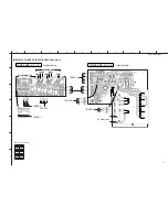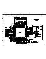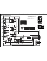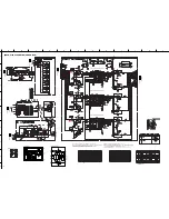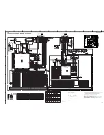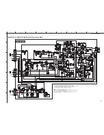
DVR-S100 SCHEMATIC DIAGRAM (SUB)
DVR-S100/NX-SW100
A
1
2
3
4
5
6
7
8
9
B
C
D
E
F
G
H
I
J
K
L
104
★
All voltages are measured with a 10M
Ω
/V DC electric volt meter.
★
Components having special characteristics are marked
s
and must be replaced
with parts having specifications equal to those originally installed.
★
Schematic diagram is subject to change without notice.
–: NOT USED
O: USED / APPLICABLE
VOLUME CONTROL
VOLUME CONTROL
VOLUME CONTROL
IC800~802, 807~809:
µ
PC4570G2
Dual OP-Amp
–
+
OUT
1
–IN
1
–V
CC
+V
CC
OUT
2
1
2
3
4
5
+IN
1
–IN
2
+IN
2
–
+
6
7
8
IC803: NJM78L05A-T3
Voltage Regulator
INPUT
OUTPUT
GND
12
LIN2
9
LOUT
8
VREF
VREF
VREF
256
256
Reset
Vref
Generator
&
Reset
pulse
Generator
2
SDATAO
20
SDATAI
19
CSN
1
SCLK
16
TE
18
ZCEN
S/P
Register
Control
Register
L
Zero Cross
Detection
IC804~806: YAC520-EE2
Stereo Digital Volume Controller
11
LIN1
4
DVSS
3
DVDD
13
AVSS
6
AVDD
17
ICN
+
–
R
14
RIN2
7
ROUT
15
RIN1
+
–
16
P
age 101
to MAIN (1)
J1
P
age 101
to MAIN (1)
J4
P
age 101
to MAIN (1)
J4
P
age 101
to MAIN (1)
D7
P
age 101
to MAIN (1)
D2
P
age 101
to MAIN (1)
F1
to P
o
w
er Cab
le
CENTER
FRONT L
REAR L
AC5.6
AC7.2
AC12.0
AC6.2
AC29.1
AC
11.9
3.6
12.8
13.0
3.7
8.3
12.1
0.1
0.1
0
0.7
0
3.6
AC
7.8
0
0
0
0
0
12.0
-11.8
12.0
-11.8
0
0
0
0
0
0
0
0
5.0
0
2.5
2.5
0
0
0
12.0
2.5
2.5
0
4.9
0
4.9
2.5
2.5
5.0
0
0
4.9
0
0
2.5
0
0
2.5
2.5
0
0
0
0
0
0
0
12.0
12.0
-11.8
-11.8
2.5
2.5
0
4.9
0
4.9
2.5
2.5
5.0
0
0
4.9
0
0
2.5
0
2.5
2.5
0
2.5
2.5
0
4.9
0
4.9
2.5
2.5
5.0
0
0
4.9
0
0
2.5
0
0
0
0
0
0
0
0
-11.8
0
0
12.2
12.0
0
0
0
-11.8
0
0


