DVD
-S795/S705
2 - 5
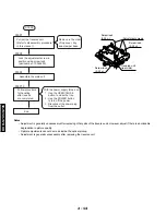
10.
Checking the Power Supply
C.B.A.
1. Remove the 3 screws.
11.
Checking the Mother C.B.A.
1. Remove the 5 screws.
2. Release the 2 tabs.
2. Carefully pull out the power supply C.B.A.
Note
There is a danger of damaging the connectors.
3. Connect the power supply C.B.A. and the mother C.B.A.
with the extension cable for inspection.
•
Extension cable: TX946360(JGS0099)(connects the power
supply C.B.A. PS1101 and the mother C.B.A. PP1101)
3. Checked by connecting the module C.B.A. and the mother
C.B.A. with the extension cables.
Extension cables: TBD (two)
Module C.B.A. Mother C.B.A.
PS3201–PP3201
PS4201–PP4201
Note
Be sure to intialize the player whenever you replace a
C.B.A. (Refer to section 1-9, Initializing the DVD player.)
12.
Checking the Power Switch C.B.A.
1. Remove the 2 screws.
13.
Checking the Front Switch C.B.A.
1. Remove the 9 screws.
14.
Checking the Headphone C.B.A.
1. Remove the 2 screws.
Summary of Contents for DVD-S795
Page 7: ...DVD S795 S705 1 5 REAR PANELS U C models DVD S795 S705 B G models G model Gold A model...
Page 39: ...3 3 3 4 BLOCK DIAGRAM 1 OVERALL BLOCK DIAGRAM...
Page 40: ...3 5 2 SERVO BLOCK DIAGRAM 3 6...
Page 41: ...3 7 3 VIDEO BLOCK DIAGRAM 3 8...
Page 42: ...3 9 4 AUDIO BLOCK DIAGRAM 3 10...
Page 60: ...9 0 0 0 0 0 8 9 0 0 3 45 18 FRONT SW HEAD PHONE POWER SW SCHEMATIC DIAGRAM 3 46...


