


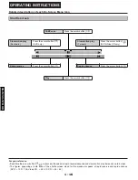


DVD-S795/S705
2 - 11
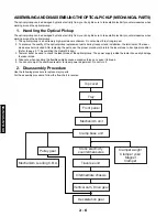
10.
Disassembling the Nut Unit
1. Remove the screw.
Notes
•
The nut unit is not part of the optical pickup.
Before replacing the optical pickup, remove the nut
unit for use with the new optical pickup.
•
After installation, use screw lock to lock the screw in
position.
•
When reassembling, use screw lock to lock the screw
in position after attaching it.
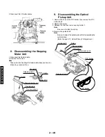
11.
Disassembling the Sub-Shaft
Preload Spring
1. Remove the screw.
Notes
•
Handle the sub-shaft preload spring carefully because
the shape of the tip is easily deformed.
•
The sub-shaft preload spring is not part of the optical
pickup. Before replacing the optical pickup, remove
the sub-shaft preload spring for use with the new
optical pickup.
•
After installation, use screw lock to lock the screw in
position.
12.
Assembling the Optical Pickup
1. Install the optical pickup.
Note
Take care not of attach the tilt spring and guide shaft in
the wrong order.
2. Fit the protruding part of the pickup FPC into the convexpart
of the FPC holder to install it.
Nut spring
Nut
screw
Nut unit
Optical pickup
(Rear surface)
Spring holder 1
Traverse chassis
Adjustment screw
Tilt spring
Guide shaft
Protruding part
Optical pickup unit
Tilt spring
Spring holder 1
Screw
Guide shaft
Tab
Traverse chassis
FPC holder
Protruding part
Pickup FPC
Hook
FPC holder
Pickup FPC
Opening
Traverse chassis
Screw
Sub-shaft preload spring
(Rear surface)
Optical pickup
Summary of Contents for DVD-S795
Page 7: ...DVD S795 S705 1 5 REAR PANELS U C models DVD S795 S705 B G models G model Gold A model...
Page 39: ...3 3 3 4 BLOCK DIAGRAM 1 OVERALL BLOCK DIAGRAM...
Page 40: ...3 5 2 SERVO BLOCK DIAGRAM 3 6...
Page 41: ...3 7 3 VIDEO BLOCK DIAGRAM 3 8...
Page 42: ...3 9 4 AUDIO BLOCK DIAGRAM 3 10...
Page 60: ...9 0 0 0 0 0 8 9 0 0 3 45 18 FRONT SW HEAD PHONE POWER SW SCHEMATIC DIAGRAM 3 46...


