background image

16

Detailed Parameter Settings

MIDI Merge Settings

If you want MIDI signals received by the BBT500H’s MIDI IN jack trans-

mitted without alteration to other MIDI devices connected to the BBT500H’s

MIDI OUT jack, set the MIDI Merge to “on”, if not, set it to “oFF”.

1

Press and hold the [FUNCTION] switch for more than three sec-

onds (until “

utL

” appears on the display) to enter the Utility Mode.

2

While holding the [MANUAL] switch, press Memory Switch [4].

The current MIDI Merge setting appears on the display (after a

few seconds the display will return to “

utL

”).

3

Use Memory Switches [1] and [2] to set MIDI Merge either “on”

(Memory Switch [2]) or “oFF” (Memory Switch [1]).

4

Press the [FUNCTION] switch to enter the Amp Mode.

MIDI Bulk Out

You can use the MIDI Bulk Out operation to back up data saved in the

BBT500H (data in memory 1-5 and Utility Mode settings) to a device

that can save MIDI data (such as a Yamaha MDF3, etc.).

1

Using a MIDI cable, connect the MIDI OUT jack on the BBT500H

to the MIDI IN jack on an external MIDI device.

* Use only a standard MIDI cable that is less than 15 meters in length. Use

of a longer cable can result in trouble such as abnormal operation, etc.

2

Hold the [FUNCTION] switch for more than three seconds (un-

til “

utL

” appears on the display) to enter the Utility Mode.

3

While holding the [MANUAL] switch, press Memory Switch [5].

The type of data to be sent with the Bulk Out operation ap-

pears on the display (after a few seconds the display will re-

turn to “

utL

”).

MIDI IN

MIDI OUT

External MIDI Device

MIDI Cable

BBT500H

Rear Panel

4

Use Memory Switches [1] and [2] to set the type of data (1-5,

ALL) to be sent with the Bulk Out operation.

1-5 ...... Sends only the data from the selected memory number.
ALL ..... Sends all data in memory numbers 1-5 and Utility Mode

settings.

5

Press Memory Switch [5] to carry out the Bulk Out operation.

While the Bulk Out operation is in progress, all lamps on the

unit will light.

* The device number becomes the MIDI receive channel number (

 pg.

15). When the MIDI receive channel is set to “ALL” (Omni ON), the

channel is set to 1.

6

Press the [FUNCTION] switch to enter the Amp Mode.

About MIDI Control Changes

You can control the overall volume of the BBT500H by con-

necting an external MIDI device’s MIDI OUT jack to the

BBT500H’s MIDI IN jack, and transmit Number 7 Control

Change Messages (Main Volume) to the BBT500H.

* With the exception of the Number 7 Control Change, the BBT500H

does not recognize any other MIDI Control Change messages.

* The Main Volume data will not change, even if a different memory

number is selected.

* When the POWER is switched ON, the Main Volume data is set

to its MAX value.

* After the Main Volume data is changed, and the external MIDI device

is disconnected, the pre-amp’s volume level may not be sufficient. If

this case occurs, transmit a Control Change with a higher volume

setting again, or switch the POWER OFF and then back ON.

About MIDI Bulk In

Using a MIDI cable, connect the MIDI IN jack on the BBT500H

to the MIDI OUT jack on an external MIDI device to return data

that has been stored on the external device, to the BBT500H’s

memory. This operation is referred to as MIDI Bulk In.

* The device number becomes the MIDI receive channel number

(

 pg. 15). When the MIDI receive channel is set to “ALL” (Omni

ON), the channel is set to 1. When set to “oFF” (OFF) data will

not be received.

* “Ld” appears on the display while receiving MIDI Bulk data.

Sending/Receiving MIDI Data Between
Two BBT500Hs

The MIDI Bulk In or MIDI Bulk Out operations can be used to

copy memory or Utility Setup data in one BBT500H to another

BBT500H.

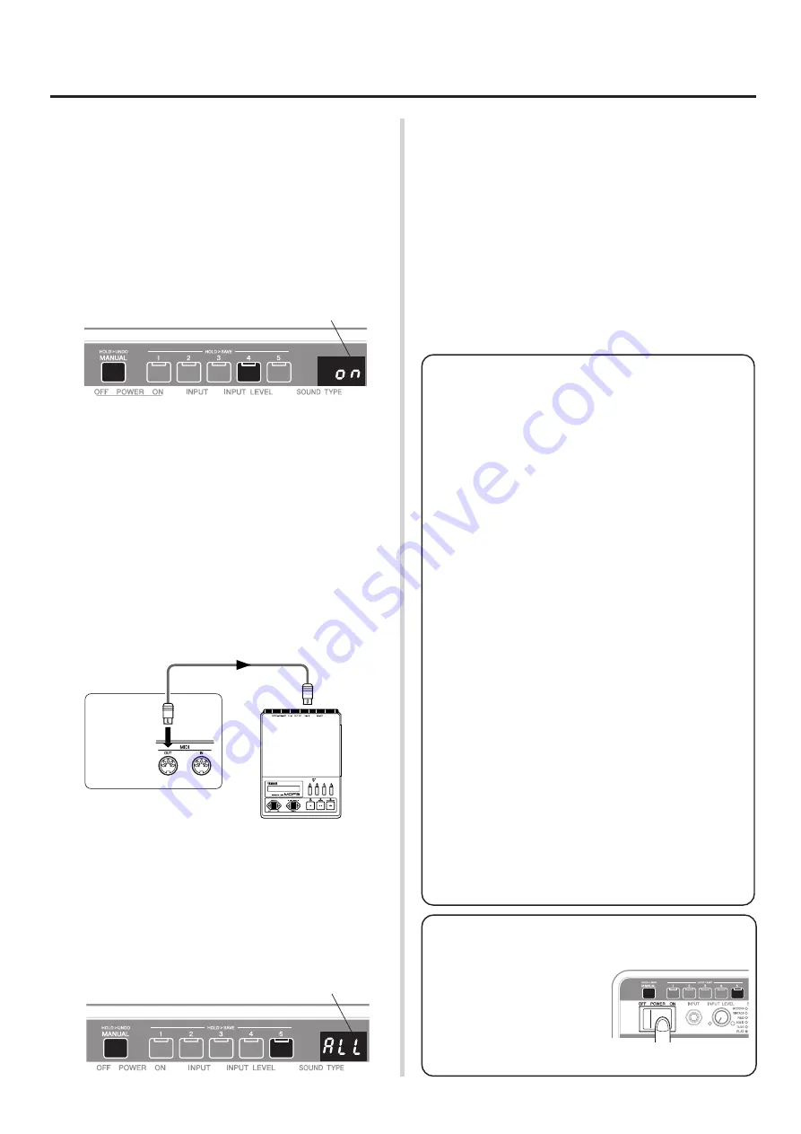
MIDI Merge Setting

Type of data to be sent with
the Bulk Out operation.

Restoring the Factory Presets

This operation clears the contents

of the BBT500H’s memory 1-5

and restores all parameters to

their factory preset settings.

While holding the [MANUAL]

switch and Memory Switch [5],

switch the POWER switch ON.

Summary of Contents for BBT 500H

Page 1: ...Owner s Manual Mode d emploi Bedienungsanleitung BASS AMPLIFIER BBT500H Manual del Usuario Handleiding Manuale di Istruzioni ...

Page 2: ...th these require ments provides a reasonable level of assurance that your use of this product in a residential environment will not result in harmful interference with other electronic devices This equipment generates uses radio frequencies and if not in stalled and used according to the instructions found in the users manual may cause interference harmful to the opera tion of other electronic dev...

Page 3: ...PORTANT SAFETY INSTRUCTIONS 10 Protect the power cord from being walked on or pinched particularly at plugs convenience receptacles and the point where they exit from the apparatus 11 Only use attachments accessories specified by the manufacturer 12 Use only with the cart stand tripod bracket or table specified by the manufacturer or sold with the apparatus When a cart is used use caution when mov...

Page 4: ...he name plate and serial number label Information such as model number power requirements serial number etc can be found at these two locations You should record the model number serial number and the date of purchase in the spaces provided below and retain this manual as a permanent record of your purchase See rear of Amplifier for graphic symbol markings The exclamation point within the equi lat...

Page 5: ...bed below Never place the device on its back side or upside down Install the device in anything other than the specified rack such in a narrow bookshelf in an small enclosed space or a place with poor ventilation etc Cover the device with a cloth or place the device on a carpet or bed When the devices is installed in an audio rack etc make sure that there is sufficient space between the wall or ot...

Page 6: ...emory locations that let you store up to five tone settings for instant recall at the press of a switch It also offers MIDI compatibility and a bi amp system using two amplifiers to create a single system etc that make it an excellent choice for use in the studio or live performances In order to get the most out of your BBT500H and its sophisticated functions please thoroughly read this Owner s Ma...

Page 7: ...ume level of the 1 band graphic equalizer pg 13 In the Compressor Mode this knob is used to adjust the compressor s attack ATTACK time pg 13 i Tone Controls BASS LOW MID MIDDLE HIGH MID TREBLE Adjusts the level of their corresponding frequencies In the Equalizer Mode these knobs are used to set the center frequency FREQ for their corresponding tone control pg 13 In the Compressor Mode these knobs ...

Page 8: ...onnect a pair of headphones to the unit It carries the same signal that is delivered from the LINE OUT jack Use the LEVEL control to adjust the volume 7 Headphones Line Out Level Control LEVEL Adjusts the output level of the PHONES jack and the LINE OUT jacks The same setting is applied to both jacks 8 Line Out Jack UNBALANCED OUT BALANCED OUT These jacks carry the signal that is selected with the...

Page 9: ...an external MIDI device that can save MIDI data such as a MIDI data filer etc and save patch data from the BBT500H to an external device pg 16 MIDI Bulk Out Also when MIDI Merge is set ON MIDI data received from an external MIDI device via the MIDI IN jack is transmitted from the MIDI OUT jack without alteration pg 16 3 MIDI IN Jack Connect this jack to the MIDI OUT jack on MIDI Foot Controller et...

Page 10: ...5dB to 15dB 0 2dB step 0 TREBLE Treble Frequency 15dB to 15dB 0 2dB step 1 OUTPUT Sets the output level Getting sound output 1 First make sure that the POWER switch is switched OFF then connect your bass to the INPUT Jack on the front panel 2 Rotate the OUTPUT knob fully to the left and then switch the POWER switch ON To protect the speakers make sure that the OUTPUT knob is set to 0 whenever swit...

Page 11: ... memory etc it may be that the knob s actual position differs from the value set in the recalled patch In this case the BBT500H is programmed to flash the patch s value on the display without changing it or the sound until the knob s position corresponds to the value in the recalled patch setting If the display flashes when rotating the knob continue rotating the knob until its position matches th...

Page 12: ...e manner it is labeled on the panel In the Amp Mode the knob s value or patch s setting value is shown on the display when the knob is turned After the BBT500H s power is switched ON or the MANUAL switch is pressed nothing is shown in the display until a Memory is recalled or a mode other than the Amp Mode is selected Enter the Amp Mode using one of the following methods The Amp Mode is the defaul...

Page 13: ...sound soft knee compression o HIGH MID N GATE Noise gate threshold level OFF 53dB to 0dB 1dB step When the input signal s level falls below this set level the noise gate acti vates cutting off the signal 0 TREBLE BLEND Blend level between the effect loop s RETURN signal and the dry signal the sound created in the BBT500H 0 Return 0 Dry 100 to 100 Return 100 Dry 0 1 OUTPUT Sets the output level The...

Page 14: ...e MANUAL switch and Memory Switches 1 through 5 to set individual MIDI settings MIDI Settings pg 15 q w e When the COMP knob is used when setting the crossover filter the setting s value is shown in the display Other than that only utL appears on the display Individual MIDI Settings Crossover Filter By connecting two BBT500Hs as shown in the illustration below you can create a bi amplified system ...

Page 15: ...y No 1 1 2 2 3 3 4 4 5 5 6 1 7 2 8 3 What is a Program Change Map A Program Change Map assigns a program change number re ceived via MIDI to a memory number For example when the BBT500H receives Program Change Number 1 from an external MIDI device it will recall memory number 3 This is also called a Program Change Table 3 1 Press and hold the FUNCTION switch for more than 3 sec onds until utL appe...

Page 16: ...he Bulk Out operation is in progress all lamps on the unit will light The device number becomes the MIDI receive channel number pg 15 When the MIDI receive channel is set to ALL Omni ON the channel is set to 1 6 Press the FUNCTION switch to enter the Amp Mode About MIDI Control Changes You can control the overall volume of the BBT500H by con necting an external MIDI device s MIDI OUT jack to the B...

Page 17: ...er tighten the screws when reattaching the carrying handle to the device Doing so can result in damage to the carrying handle Air Flow The device utilizes a forced air cooling system which cools the interior of the unit by drawing air through the front intake by the fan which push the air out the back Intake Exhaust Cooling fan Front panel Side view Rear view Carrying Handle Set Rack Mount Adaptor...

Page 18: ...p on the instrument connected to the INPUT jack Are the INPUT LEVEL GAIN MASTER OUTPUT control knobs set to 0 Check the Effect Loop s BLEND setting Compressor Mode TREBLE control knob Unless an external effector is connected to the device raising the BLEND control will result in lowering the original sound If the BLEND control is set to 100 the original sound will not be produced Sound output is l...

Page 19: ...x2 Green Red Connections INPUT Standard Monaural Phone Jack SPEAKER 1 2 Standard Monaural Phone Jack PHONES Standard Stereo Phone Jack LINE OUT UNBALANCED OUT Standard Monaural Phone Jack LINE OUT BALANCED OUT XLR Jack FX LOOP SEND RETURN Standard Monaural Phone Jack TUNER OUT Standard Monaural Phone Jack MIDI IN MIDI OUT 5 pin DIN jack A D Conversion 24 bit D A Conversion 24 bit Sampling Frequenc...

Page 20: ... x Note OFF x x After Key s x x Touch Ch s x x Pitch Bender x x 0 6 x x 7 x o Main Volume 8 127 x x Control Change Prog x o 0 127 Program Change Change True Number 1 128 System Exclusive o o Bulk Dump System Song Pos x x Song Sel x x common Tune x x System Clock x x Real Time Commands x x Aux All Sound OFF x x Reset All Cntrls x x Local ON OFF x x All Notes OFF x x Mes Active Sense o x sages Reset...

Page 21: ...WC95000 Printed in China ...

Reviews: