background image


Controls and Functions


16


AUDIOGRAM 6 Owner’s Manual


7


COMP Control


Adjusts the amount of compression applied to the chan-
nel. As the knob is turned to the right, the interface
automatically raises the compression ratio while adjust-
ing the output gain accordingly. The result is smoother,
more even dynamics because louder signals are atten-
uated while the overall level is boosted.

Avoid setting the compression too high, as 
the higher average output level that results 
may lead to feedback.


8


MONO/STEREO Switch


This switch allows channels 1 and 2 to be used either
as separate mono channels or as a stereo pair. When
set to MONO (

), channels 1 and 2 function as inde-

pendent mono channels feeding both the L and R STE-
REO OUT jacks 


3


. When set to STEREO (

), input

channels 1 and 2 function as a stereo pair: the channel
1 signal feeds the L STEREO OUT jack and the chan-
nel 2 signal feeds the R STEREO OUT jack. 


9


PEAK Indicators


The PEAK indicators light when the channel signal
reaches or exceeds clipping level. Note that signal lev-
els as indicated by the PEAK indicators are affected by
both the GAIN and LEVEL controls.
If a PEAK indicator lights, adjust the GAIN 


6


  and

COMP 


7


 controls to lower the level so that the indica-

tor goes out.


0


LEVEL Controls


Adjusts the level of the channel signal. Use these con-
trols to adjust the balance between the various chan-
nels.


A


POWER Indicator


This indicator lights when power is applied to the
AUDIOGRAM interface via the USB cable (supplied)
that connects it to the computer.


B


P48V (CH1) Switch/Indicator 
(only for channel 1)


This switch toggles phantom power on and off. If you
set the switch on (

), the AUDIOGRAM supplies

phantom power to channel 1 MIC/INST jack (XLR-type)


1


. Turn this switch on when using a phantom-powered

condenser microphone.


• Be sure to leave this switch off (

) if 

you do not need phantom power.

• When turning the switch on, be sure that 

only a condenser microphone is con-
nected to the channel 1 MIC/INST input 
jack. Other devices may be damaged if 
connected to phantom power. This precau-
tion does not apply to balanced dynamic 
microphones or instruments with the 
phone jack, however, as these will not be 
affected by phantom power.

• To prevent damage to speakers, be sure to 

turn off power amplifiers (or powered 
speakers) before turning this switch on or 
off. We also recommend that you set the 
MASTER LEVEL control to the minimum 
position. Neglect of these precautions may 
result in large noise bursts that may dam-
age your equipment, your ears, or both.


C


Level Indicators


These indicators show signal levels prior to the MASTER
LEVEL control 


E


. The SIGNAL LED lights when a signal

is present, and the PEAK LED lights when the signal
reaches or exceeds clipping level.  Adjust the input chan-
nel LEVEL controls 


0


 so that the PEAK LEDs flash only

briefly on occasional high-level peaks or not at all.


D


DAW Control


Adjusts the level of the signal received from Cubase AI
sent to the AUDIOGRAM STEREO OUT jacks 


3


.


E


MASTER LEVEL Control


Adjusts the signal level sent to the STEREO OUT jacks


3


. This allows you to adjust the overall volume without

changing the relative volume balance among the chan-
nels.


F


USB Connector


Connects the AUDIOGRAM interface to a USB port on
your computer via the supplied USB cable. In addition
to transferring audio data between the AUDIOGRAM
interface and the computer, the USB cable supplies
power from the computer to the AUDIOGRAM interface.


When connecting or disconnecting the USB 
cable be sure to turn the DAW control and the 
MASTER LEVEL control all the way down.


Yamaha recommends that you use a USB 
cable with a length of 1.5 meter or less.


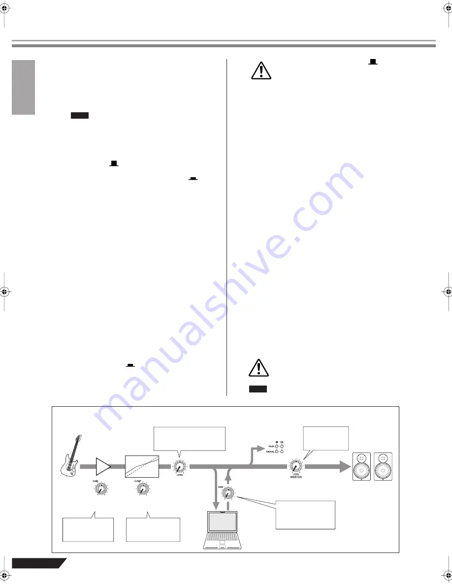
Input Signal Flow

NOTE

CAUTION

CAUTION

NOTE

Input

Output

Adjust for maxi-
mum level with 
minimum noise.

Compress the sig-
nal for increased 
subjective level.

Adjust the recording level 
as well as the balance 
between channels.

Adjusts the 
monitor level.

Adjusts the playback 
level from Cubase AI 
(does not affect the 
record level).

Record

Playback

E

 MASTER 

LEVEL control

D

 DAW 

control

0

 LEVEL 

controls

7

 COMP 

controls

6

 GAIN 

controls

C

 Level

indicator

Cubase AI

audiogram6̲en.book Page 16 Wednesday, April 2, 2008 3:46 PM

Summary of Contents for Audiogram6

Page 1: ...Owner s Manual Bedienungsanleitung Mode d emploi Manual de instrucciones Руководство пользователя 取扱説明書 USB AUDIO INTERFACE Русский English Deutsch Français Español 日本語 USB AUDIO INTERFACE ...

Page 2: ... determined by turning the unit OFF and ON please try to eliminate the problem by using one of the following measures Relocate either this product or the device that is being affected by the interference Utilize power outlets that are on different branch cir cuit breaker or fuse circuits or install AC line filter s In the case of radio or TV interference relocate reori ent the antenna If the anten...

Page 3: ...damage the speakers Do not expose the device to excessive dust or vibrations or extreme cold or heat such as in direct sunlight near a heater or in a car during the day to prevent the possibility of panel disfiguration or damage to the internal components Do not place the device in an unstable position where it might accidentally fall over Do not use the device in the vicinity of a TV radio stereo...

Page 4: ...re This disk containing the software is not meant for use with an audio visual system CD player DVD player etc Do not attempt to use the disk on equipment other than a computer Future upgrades of application and system software and any changes in specifications and functions will be announced separately The screen displays as illustrated in this manual are for instructional purposes and may appear...

Page 5: ... tage of your interface s superlative features and enjoy trouble free operation for years to come After reading the manual please store it in a safe place Connect To Your Computer via a Single USB Cable page 8 The AUDIOGRAM interface connects to your com puter via the supplied USB cable Stereo audio data is transferred in both directions from the interface to the computer and vice versa via the US...

Page 6: ...Memory 1 GB or more Computer Windows based computer with built in USB interface OS Windows XP Professional XP Home Edition CPU 750 MHz or higher Intel Core Pentium Celeron processor Memory 96 MB or more 128 MB or more rec ommended Computer Macintosh computer with built in USB interface OS Mac OS X 10 3 3 or higher CPU Macintosh G3 300 MHz or higher Intel processor Memory 128 MB or more OS Windows ...

Page 7: ... Keyboard etc Computer Headphones Powered speakers To connect a device such as a microphone To connect an instrument such as an electric guitar or bass USB cable Cubase AI Be sure to turn the PHANTOM 48V switch on when using a phantom powered condenser microphone ...

Page 8: ... support and other benefits you will need to register the software and activate your software license by starting it while the computer is connected to the Internet Click the Register Now button shown when the software is started then fill in all required fields for registration If you do not register the product you will be unable to use the application after a limited period of time expires 1 Tu...

Page 9: ...change the connection to a different USB port a driver installation dis play may appear If this occurs wait until the installation is complete before proceeding 4 Turn the power to the monitor speakers powered speakers 1 Set the GAIN controls to the minimum position and the LEVEL controls to about 1 o clock Set the MASTER LEVEL control to the mini mum position Failure to do so may result in loud n...

Page 10: ...cation Create a Cubase AI shortcut or alias on your desktop so you can easily launch the pro gram when required 3 Select Device Setup from the Device menu to open the Device Setup window Windows Select VST Audio System in the Device field on the left side of the window Select ASIO DirectX Full Duplex Driver in the ASIO Driver field on the right side of the window A dialog box will appear asking Do...

Page 11: ...es not change close and restart the Cubase AI then open the Device Setup window The input ports may not be shown if you are using Windows Vista If so refer to the The input ports are not shown section in the Troubleshooting section page 17 7 Select New Project from the File menu to create a new project file The new project dialog window will open For this example select CAI4 4 Stereo 8 Mono Audio ...

Page 12: ...ce Select Ste reo In 1 for a stereo track and Left Right Stereo In 1 for a monaural track 3 Make sure the Record Enable button for the track to be recorded is turned on If the Record Enable button is off click it to turn it on 4 Play the instrument to be recorded and adjust the AUDIOGRAM GAIN controls and LEVEL controls so that the Clipping indica tor never lights 5 Specify the point at which you ...

Page 13: ...ce adjust the volume with the DAW control and MASTER LEVEL control The playback level will approximately match the recording level when the DAW control is set to about 1 o clock 5 To save the project file select Save from the File menu and enter a file name before actu ally saving the file Save your project file frequently to insure against los ing large amounts of data if a problem occurs 6 Repea...

Page 14: ... of the channel strip to open the VST audio channel settings window Click Insert 1 and select Earlier VST Plug ins Reverb RoomWorks SE For further details refer to the pdf manual pro vided with the Cubase AI software It s a good idea to lower the channel fader a bit before adding an effect since the effect can cause an increase in the overall channel level 6 When the final mix adjustments have bee...

Page 15: ... Jacks These output the mixed signal from channels 1 to 5 6 The output level can be adjusted using the MASTER LEVEL control These jacks would typically be con nected to monitor speakers powered speakers 4 PHONES Jack Connects a pair of headphones to this jack The PHONES jack outputs the same signal as the STEREO OUT jacks 5 MIC INST Switch Set this switch according to the type of device con nected...

Page 16: ...he channel 1 MIC INST input jack Other devices may be damaged if connected to phantom power This precau tion does not apply to balanced dynamic microphones or instruments with the phone jack however as these will not be affected by phantom power To prevent damage to speakers be sure to turn off power amplifiers or powered speakers before turning this switch on or off We also recommend that you set...

Page 17: ...whether the USB Audio CODEC icon is checked If not right click the USB Audio CODEC icon and select Set as Default Device 3 Click the Recording tab and check whether the USB Audio CODEC icon is checked If not right click the USB Audio CODEC icon and select Set as Default Device Windows XP 1 From the START menu click Control Panel then double click the Sounds and Audio Devices icon to open the Sound...

Page 18: ...ording or playing long continuous sec tions of audio The audio data processing capabilities of your com puter will depend on a number of factors including CPU speed and access to external devices On Windows XP computers changing some settings as outlined below can improve performance 1 Click Control Panel from the START menu and double click the Sounds and Audio Devices icon to open the Sounds and...

Page 19: ... for CH 1 2 MONO STEREO Switch x 1 MONO CH 1 2 signals fuction as independent mono channels STEREO CH 1 2 signals fuction as a stereo pair LEVEL Control x 4 Adjust the level of CH 1 5 6 PHANTOM 48V Switch x 1 48 V only for CH1 DAW Control x 1 Adjusts the DAW playback signal MASTER LEVEL Control x 1 Adjusts the overall signal Indicators Level Indicators x 1 2 points green red PEAK Indicator x 4 Red...

Page 20: ...u HA HA Gain 6 to 50dB 6dBu 6dBu 22dBu BA BA ST CH Level PEAK RE LINE L MONO CH3 34 to 10dBu ST CH INPUT CH3 4 LINE R CH4 34 to 10dBu LINE L MONO CH5 34 to 10dBu ST CH INPUT CH5 6 LINE R CH6 34 to 10dBu USB REG USB AUDIO LO RO LIN D D Vbus 5V IN DC DC 5V GR DAW RE POWER PHANTOM 48V 7 5V 7 5V DC DC DC DC OUT1 OUT2 SW_IC EN1 EN2 3 7V GND LPF LPF LPF LPF RIN 12MHz SSPND STEREO L STEREO R ST CH IN LIN...

Page 21: ...cessory disk is provided by Steinberg on its website at the follow ing address http www steinberg net You can visit the Steinberg site also via the Help menu of the included DAW software The Help menu also includes the PDF manual and other information on the software ATTENTION SOFTWARE LICENSE AGREEMENT PLEASE READ THIS SOFTWARE LICENSE AGREEMENT AGREEMENT CAREFULLY BEFORE USING THIS SOFT WARE YOU...

Page 22: ...ged by accident abuse or misapplication TO THE FULLEST EXTENT PERMITTED BY LAW YAMAHA EXPRESSLY DISCLAIMS ANY IMPLIED WARRANTIES ON THE TAN GIBLE MEDIA INCLUDING THE IMPLIED WARRANTIES OF MERCHANTABILITY AND FITNESS FOR A PARTICU LAR PURPOSE 5 DISCLAIMER OF WARRANTY ON SOFTWARE You expressly acknowledge and agree that use of the SOFTWARE is at your sole risk The SOFTWARE and related documentation ...

Page 23: ...i Most street Moscow 107996 Russia Tel 495 626 0660 OTHER EUROPEAN COUNTRIES Yamaha Music Central Europe GmbH Siemensstraße 22 34 25462 Rellingen Germany Tel 49 4101 3030 Yamaha Corporation Asia Pacific Music Marketing Group Nakazawa cho 10 1 Naka ku Hamamatsu Japan 430 8650 Tel 81 53 460 2313 TURKEY CYPRUS Yamaha Music Central Europe GmbH Siemensstraße 22 34 25462 Rellingen Germany Tel 04101 3030...

Page 24: ...Yamaha Web Site English only USB AUDIO INTERFACE ...

Reviews: