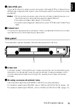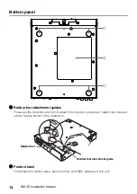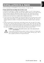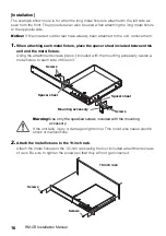
10
RM-CR Installation Manual
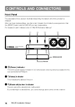
Front Panel
The explanation here uses an illustration depicting the state in which the product is
shipped.
After you have made settings, use the screw to fasten the included access panel so that
the [RESET] button and the [SETUP] port are inaccessible.
For details on each indicator, refer to “RM-CR Reference Manual.”
1
(Power) indicator
This is the power supply indicator. It is lit when power is being correctly supplied to the
rear panel [Dante/PoE] port.
2
(Status) indicator
This indicates the status of the unit.
3
(Bluetooth) button / indicator
Press to pair with a smartphone via Bluetooth.
By connecting to a smartphone, you can exchange audio with a remote location.
CONTROLS AND CONNECTORS
1
2
3
4
5
6
Access panel
Screw
Summary of Contents for ADECIA RM-CR
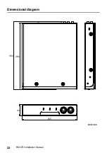
Page 22: ...22 RM CR Installation Manual Dimensional diagram 264 260 44 215 Unit mm ...
Page 42: ...42 RM CR Installationshandbuch Maßbild 264 260 44 215 Einheit mm ...
Page 62: ...62 Manuel d installation du RM CR Schéma dimensionnel 264 260 44 215 Unité mm ...
Page 82: ...82 Manual de instalación del RM CR Diagrama de dimensiones 264 260 44 215 Unidad mm ...
Page 102: ...102 RM CR Manual de Instalação Diagrama dimensional 264 260 44 215 Unidade mm ...
Page 122: ...122 Manuale di installazione RM CR Diagramma dimensioni 264 260 44 215 Unità mm ...
Page 142: ...142 Руководство по установке RM CR Схема размеров 264 260 44 215 Единица измерения мм ...
Page 162: ...162 RM CR 安装说明书 尺寸图 264 260 44 215 单位 mm ...
Page 168: ...168 RM CR 설치설명서 해당 무선 설 비는 운용 중 전파혼신 가능성이 있음 ...
Page 182: ...182 RM CR 설치설명서 치수도 264 260 44 215 단위 mm ...

