– 87 –
CHAS
• [C] Determining the cause and location of the malfunction
• [C-1] Only the ABS warning light does not come on when the main switch is set to “ON”
NOTE:
_
Check following the steps in sequence.
1. Visual check
1) Check the ABS fuse.
Determine the cause of the blown fuse and repair. Replace with a new fuse. (Refer to “CHECK-
ING THE FUSES” in chapter 3. [Manual No.: 5JW1-AE1])
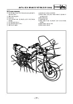
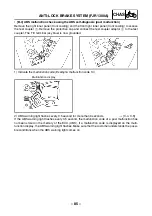
2) Check the sub-wire harness (ABS) and wire harness couplers.
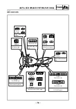
Check that the sub-wire harness (ABS) couplers are securely connected to the wire harness cou-
plers. Both harnesses are connected by three couplers. (Refer to “ABS COUPLERS”.)
3) Check the connection of the sub-wire harness (ABS) to the ECU (ABS).
Check that the sub-wire harness (ABS) is securely connected to the ECU (ABS). (Refer to “ABS
COUPLERS”.)
2. Confirmation using the test coupler adaptor
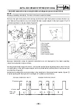
1) Connect the test coupler adaptor to the test coupler. (Refer to “[B-5] ABS malfunction check
using the ABS self-diagnosis (present malfunction)”.)
2) Ground the warning light terminal (white/red) of the test coupler adaptor or connect the warning
light terminal to the negative battery terminal.
• If the ABS warning light comes on, the sub-wire harness (ABS) may be disconnected.
• If the ABS warning light does not come on, the ABS warning light lead may be disconnected or
the contact of the ABS warning light may be defective.
3) Remove the ECU (ABS) coupler and check the ECU (ABS) coupler and test coupler adaptor
ends of the white/red lead for continuity. (Refer to “ABS COUPLERS”.)
• If there is continuity, the ECU (ABS) is defective.
→
Replace the ECU (ABS). (Refer to “[D-1]
Maintenance of the ECU (ABS)”.)
• If there is no continuity, the warning light circuit in the sub-wire harness (ABS) is defective. Dis-
connection or short
→
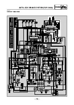
Correct. (Refer to “CIRCUIT DIAGRAM”.)
• [C-2] ABS warning light and all other indicators do not come on
NOTE:
_
Check following the steps in sequence.
1. Check the power supply system.
1) Check that the battery is connected correctly.
2) Check the battery voltage. (Refer to “CHECKING AND CHARGING THE BATTERY” in chapter
3. [Manual No.: 5JW1-AE1])
3) Check if the main fuse is blown. If the main fuse is blown, determine the cause and repair.
Replace with a new fuse. (Refer to “CHECKING THE FUSES” in chapter 3.
[Manual No.: 5JW1-AE1])
2. Check the connections.
1) Check that the main fuse coupler is securely connected.
2) Check that the wire harness is securely connected to the sub-wire harness (ABS).
3) Check that the main switch coupler is securely connected.
4) Check that the meter assembly coupler is securely connected. (Refer to “ABS COUPLERS”.)
When these checks are finished, return to [A] and check the ABS again.
ANTI-LOCK BRAKE SYSTEM (FJR1300A)
Summary of Contents for 2003 FJR1300
Page 1: ...2003 FJR1300 R FJR1300A R 5JW1 AE4 SUPPLEMENTARY SERVICE MANUAL ...
Page 2: ......
Page 159: ......
Page 160: ...YAMAHA MOTOR CO LTD 2500 SHINGAI IWATA SHIZUOKA JAPAN ...

