background image

– 51 –

CHAS

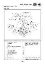
FRONT WHEEL AND BRAKE DISCS

EAS00514 

CHASSIS

FRONT WHEEL AND BRAKE DISCS

Order

Job/Part

Q’ty

Remarks

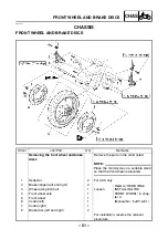
Removing the front wheel and brake
discs

Remove the parts in the order listed.

NOTE:


Place the motorcycle on a suitable stand
so that the front wheel is elevated. 

1

Reflector

2

For AUS only

2

Brake caliper (left and right)

2

Refer to “REMOVING/
INSTALLING THE 
FRONT WHEEL” in chap-
ter 4. 
(Manual No.: 5JW1-AE1)

3

Wheel axle pinch bolt

1

Loosen.

4

Front wheel axle

1

5

Front wheel

1

6

Collar (left)

1

7

Collar (right)

1

8

Brake disc (left and right)

2

For installation, reverse the removal 
procedure.

Summary of Contents for 2003 FJR1300

Page 1: ...2003 FJR1300 R FJR1300A R 5JW1 AE4 SUPPLEMENTARY SERVICE MANUAL ...

Page 2: ......

Page 3: ...Supplementary Service Manual together with the following manuals FJR1300 N 2001 SERVICE MANUAL 5JW1 AE1 FJR1300 P 2002 SUPPLEMENTARY SERVICE MANUAL 5JW1 AE2 FJR1300 R FJR1300A R 2003 SUPPLEMENTARY SERVICE MANUAL 2003 by Yamaha Motor Co Ltd First edition February 2003 All rights reserved Any reproduction or unauthorized use without the written permission of Yamaha Motor Co Ltd is expressly prohibit...

Page 4: ...els Modifications and significant changes in specifications or procedures will be forwarded to all authorized Yamaha deal ers and will appear in future editions of this manual where applicable NOTE Designs and specifications are subject to change without notice EAS00004 IMPORTANT MANUAL INFORMATION Particularly important information is distinguished in this manual by the following The Safety Alert...

Page 5: ...of each page except in chapter 3 PERIODIC CHECKS AND ADJUSTMENTS where the sub section title s appears 3 Sub section titles appear in smaller print than the section title 4 To help identify parts and clarify procedure steps there are exploded diagrams at the start of each removal and disassembly section 5 Numbers are given in the order of the jobs in the exploded diagram A circled number indicates...

Page 6: ...g fluid B Lubricant C Special tool D Tightening torque E Wear limit clearance F Engine speed G Electrical data Symbols H to M in the exploded diagrams indicate the types of lubricants and lubrication points H Engine oil I Gear oil J Molybdenum disulfide oil K Wheel bearing grease L Lithium soap base grease M Molybdenum disulfide grease Symbols N to O in the exploded diagrams indicate the following...

Page 7: ...EL TANK 44 INSTALLING THE FUEL PUMP 46 COWLINGS AND COVERS 47 COWLINGS 47 ELECTRICAL SYSTEM 50 ADJUSTING THE HEADLIGHT BEAMS 50 CHASSIS 51 FRONT WHEEL AND BRAKE DISCS 51 REAR WHEEL AND BRAKE DISC 52 INSTALLING THE BEARING 53 FRONT AND REAR BRAKES 54 REAR BRAKE MASTER CYLINDER 54 HANDLEBARS 57 RIGHT HANDLEBAR 57 ANTI LOCK BRAKE SYSTEM FJR1300A 58 ABS OUTLINE 58 ABS COMPONENTS 77 ABS COUPLERS 78 CIR...

Page 8: ...1 CHECKING THE IMMOBILIZER SYSTEM 142 ACCESSORY BOX SYSTEM 145 CIRCUIT DIAGRAM 145 TROUBLESHOOTING 146 TROUBLESHOOTING 148 TROUBLESHOOTING WITH THE ABS WARNING LIGHT 148 ONLY THE ABS WARNING LIGHT DOES NOT COME ON 148 ALL INDICATORS DO NOT COME ON 148 ABS WARNING LIGHT CONTINUES TO FLASH 148 ABS WARNING LIGHT FLASHES EVERY 0 5 SECOND 148 ABS WARNING LIGHT CONTINUES TO COME ON 148 FJR1300A WIRING D...

Page 9: ...nd assembly Use only the appropriate special tool as this will help prevent damage caused by the use of inappro priate tools or improvised techniques When placing an order refer to the list provided below to avoid any mistakes Tool No Tool name Function Illustration 90890 03149 Test coupler adaptor This tool is used to check the ABS diag nosis ...

Page 10: ...ength 2 195 mm Overall width 760 mm Overall height 1 435 mm Seat height 805 mm Wheelbase 1 515 mm Minimum ground clearance 135 mm Minimum turning radius 3 100 mm Weight Wet with oil and a full fuel tank 275 kg FJR1300 282 kg FJR1300A Dry without oil and fuel 244 kg FJR1300 251 kg FJR1300A Maximum load total of cargo rider passenger and accessories 201 kg FJR1300 194 kg FJR1300A GENERAL SPECIFICATI...

Page 11: ...perature 100 105 C Oil temperature 80 90 C Standard compression pressure at sea level 1 600 kPa 16 kg cm2 16 bar at 400 r min Engine oil Lubrication system Wet sump Recommended oil SAE 20W 40 SE SAE 10W 40 SE API service SE SF SG type or higher Quantity Total amount 4 9 L Without oil filter cartridge replace ment 3 8 L With oil filter cartridge replacement 4 L Oil pressure hot 30 kPa 0 30 kg cm2 0...

Page 12: ...low to full level 0 15 L Water pump Water pump type Single suction centrifugal pump Reduction ratio 75 48 25 28 1 395 Maximum impeller shaft tilt 0 15 mm Measurement B 24 997 25 097 mm 23 997 mm Fuel pump Pump type Electrical Model manufacturer 5JW DENSO Maximum consumption amperage 5 5 A Output pressure 294 kPa 2 94 kg cm2 2 94 bar Throttle bodies Model manufacturer quantity 42EHS MIKUNI 4 Intake...

Page 13: ...W Model manufacturer MEZ4J METZELER BT020R N BRIDGESTONE Tire pressure cold 0 90 kg 250 kPa 2 5 kgf cm2 2 5 bar 90 201 kg FJR1300 290 kPa 2 9 kgf cm2 2 9 bar 90 194 kg FJR1300A 290 kPa 2 9 kgf cm2 2 9 bar High speed riding 250 kPa 2 5 kgf cm2 2 5 bar Minimum tire tread depth 1 6 mm Front brakes Brake type Dual disc brake Operation Right hand operation Brake lever free play at lever end 7 5 16 5 mm...

Page 14: ...e No Fork oil Recommended oil Suspension oil 01 or equivalent Quantity each front fork leg 664 cm3 Level from the top of the inner tube with the inner tube fully com pressed and without the fork spring 104 mm Inner tube outer diameter 48 mm Inner tube bearing 0 2 mm Damper adjusting rod locknut dis tance 12 mm Spring preload adjusting positions Minimum 6 Standard 4 Maximum 1 Rebound damping adjust...

Page 15: ...ength 72 5 mm 71 05 mm Installed length 65 4 mm Spring rate K1 83 3 N mm 8 49 kgf mm Spring stroke K1 0 32 mm Spring rate K2 117 6 N mm 11 99 kgf mm Spring stroke K2 32 60 mm Optional spring available No Standard spring preload gas air pres sure 1 200 kPa 12 0 kg cm2 12 0 bar Spring preload adjusting positions Rider only SOFT With passenger or cargo HARD Rebound damping adjusting posi tions Minimu...

Page 16: ...or light voltage wattage quantity Neutral indicator light 14 V 1 12 W 1 Turn signal indicator light 14 V 1 4 W 2 Oil level warning light 14 V 1 12 W 1 High beam indicator light 14 V 1 12 W 1 Engine trouble warning light 14 V 1 12 W 1 ABS warning light 14 V 1 12 W 1 Immobilizer system indicator light LED 1 Bulbs voltage wattage quantity Headlight 12 V 60 W 55 W 2 Auxiliary light 12 V 5 W 2 Tail bra...

Page 17: ...e 15 A Headlight fuse 25 A 1 Signaling system fuse 15 A 1 Ignition fuse 10 A 1 Radiator fan motor fuse 15 A 1 Hazard lighting fuse 7 5 A Parking lighting fuse 10 A Backup fuse odometer and clock 10 A ABS control unit fuse 7 5 A FJR1300A ABS motor fuse 30 A FJR1300A Windshield motor fuse 2 A Reserve fuse 25 A 15 A 10 A 7 5 A 2 A 1 30 A FJR1300A Item Standard Limit ELECTRICAL SPECIFICATIONS ...

Page 18: ...1300A Rear wheel sensor and sensor housing M8 30 3 0 FJR1300A Rear wheel sensor lead holder and swingarm M5 4 0 4 FJR1300A Rear brake hose hydraulic unit to rear brake caliper holder and swingarm M6 7 0 7 FJR1300A Rear brake hose rear brake master cylinder to hydraulic unit holder and frame M6 7 0 7 FJR1300A Rear brake hose rear brake master cylinder to hydraulic unit holder M6 7 0 7 FJR1300A Rear...

Page 19: ...e 4 Main switch lead immobilizer lead 5 Headlight lead 6 Fuse box 7 Thermostat assembly breather hose 8 Coolant reservoir hose 9 Hazard switch 0 Rectifier regulator A Plate B Plunger control unit hose 2 C Radiator D Radiator fan coupler E Accessory box solenoid CABLE ROUTING ...

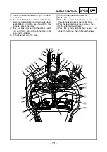
Page 20: ...nd thermostat assembly breather hose through the left slit of the plate Ë To the thermostat housing Ì After passing the coolant reservoir hose through the two hose guides behind the plate pass the hose through the right hole of the plate Í Pass plunger control unit hose 2 on the inside of the plate Î To the radiator fan Ï Pass the radiator fan lead on the outside of the plate CABLE ROUTING ...

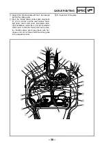
Page 21: ...k plug lead 1 A Ignition coil leads 1 and 4 B Front turn signal extension lead C Ignition coils 1 and 4 D Coolant reservoir E Coolant reservoir breather hose F Coolant reservoir hose G Pickup coil lead H O2 sensor lead I Starter motor lead J Spark plug lead 2 K Spark plug lead 3 L Ignition coils 2 and 3 M Ignition coil leads 2 and 3 N Starter relay O Negative battery lead CABLE ROUTING ...

Page 22: ... ignition coil leads 1 and 4 can be turned outward Ì Support the coolant reservoir breather hose with the hose holder attached to the coolant reser voir Í Pass the brake hose through the brake hose holder Î Pass the coolant reservoir hose through the hole of the plate Ï Pass the coolant reservoir hose through the hose guide attached to the coolant reservoir Ð Pass the negative battery lead and sta...

Page 23: ...lant reservoir breather hose holder Ó Fasten spark plug leads 1 and 4 at the num ber mark Ô Pass the wire harness spark plug leads 1 2 3 and 4 through the right slit of the battery bracket Õ Pass the starter motor lead negative battery lead wire harness and spark plug leads 2 and 3 through the battery stay Be sure to pass the starter motor lead and negative battery lead on the battery stay side CA...

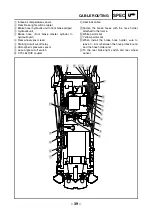
Page 24: ...r regulator 6 Clutch hose 7 Fuel tank breather hose 8 Fuel tank overflow hose 9 Stator coil lead 0 Sidestand switch A Sidestand switch lead B Oil level switch lead C Brake hose D Coolant reservoir hose E Thermostat assembly breather hose F Headlight lead G Radiator fan lead H Wire harness CABLE ROUTING ...

Page 25: ... wire harness with the plastic band attached to the frame Ì To the fuel tank Í Pass the stator coil lead through the fork in the wire harness Î Fasten the clutch hose with the hose holder attached to the frame Ï Insert the harness holder into the hole at the rear end of the frame Ð Pass the brake hose through the brake hose holder Ñ To the wire harness Ò Contact the clutch hose to the turn stopper...

Page 26: ...ead to the frame with a plastic locking tie Ì Pass the tail brake light lead between the rear cover and frame Í Pass the wire harness on the inside of the seat lock cable Î Fasten the wire harness and wire harness ECU with the clamp attached to the clamp bracket which is attached to the seat lock bracket Ï Pass the air filter case breather hose fuel tank breather hose and fuel tank over flow hose ...

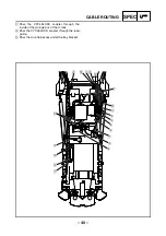
Page 27: ...ad 4 Headlight lead 5 Main switch lead 6 Immobilizer lead 7 Throttle cable 8 Right handlebar switch lead 9 T bar 0 Spark plug lead 3 A Spark plug lead 2 B Spark plug lead 1 C Spark plug lead 4 D Cable guide E Throttle position sensor F Sidestand switch lead CABLE ROUTING ...

Page 28: ...witch lead and throttle cables through the hole on the right side of the frame Ë To the lower left slit of the plate Ì To the cylinder identification sensor Í To the fuel tank Î Pass the cylinder identification sensor lead through the lead guide of throttle body Ï Pass the lead wire above the fuel return hose Ð To the sidestand switch lead Ñ Pass the cylinder identification sensor lead under the f...

Page 29: ... 2 3 and 4 and the wire harness head light lead main switch lead immobilizer lead right handlebar switch lead and left handlebar switch lead Install the thermostat heat protec tor throttle cables spark plug leads wire har nesses and air cut valve under the cable guide in the respective order Ô To the left slit of the plate CABLE ROUTING ...

Page 30: ... brake light switch É Pass the rear brake light switch through the lead guide attached to the frame Ê Pass the CYCLELOCK coupler through the inside of the storage box of the U lock Ë Pass the CYCLELOCK coupler through the lead guide Ì Pass the pressure sensor lead and lean angle circuit cut off relay lead through the lead guide Í Pass the wire harnesses under the tray bracket CABLE ROUTING ...

Page 31: ...ht lead 7 Brake hose hydraulic unit to front brake caliper 8 Right handlebar switch lead 9 Fuse box 0 Thermostat assembly breather hose A Coolant reservoir hose B Hazard switch C Rectifier regulator D Plate E Plunger control unit hose 2 F Radiator G Radiator fan coupler H Accessory box solenoid A A 1 2 3 4 5 6 7 1 2 7 8 2 7 8 1 H 0 A B C 9 D E F G È É Ê Ë Ì Í Î Ï Ñ Ò Ó A A 7 3 1 2 Õ Ô Ð ...

Page 32: ...ht handlebar switch lead through the guide Í Pass the wire harness stator coil lead coolant reservoir hose and thermostat assembly breather hose through the left slit of the plate Î To the thermostat housing Ï After passing the coolant reservoir hose through the two hose guides behind the plate pass the hose through the right hole of the plate Ð Pass plunger control unit hose 2 on the inside of th...

Page 33: ...e frame Ô Tighten the brake hose joint bolt union bolt and brake hose holder bolt in the proper tightening sequence as shown Õ When replacing the brake hoses remove the engine from the frame A A 1 2 3 4 5 6 7 1 2 7 8 2 7 8 1 H 0 A B C 9 D E F G È É Ê Ë Ì Í Î Ï Ñ Ò Ó A A 7 3 1 2 Õ Ô Ð CABLE ROUTING ...

Page 34: ...nal extension lead D Ignition coil leads 1 and 4 E Coolant reservoir F Coolant reservoir breather hose G Brake hose hydraulic unit to front brake caliper H Coolant reservoir hose I Pickup coil lead J O2 sensor lead K Starter motor lead L Spark plug lead 2 M Spark plug lead 3 N Ignition coils 2 and 3 O Ignition coil leads 2 and 3 P ABS test coupler Q Starter relay R Negative battery lead A A A A 1 ...

Page 35: ... Ì Support the coolant reservoir breather hose with the hose holder attached to the coolant reservoir Í Pass the brake hose through the brake hose holder Î Pass the coolant reservoir hose through the hole of the plate Ï Pass the coolant reservoir hose through the hose guide attached to the coolant reser voir Ð Pass the negative battery lead and starter motor lead through the hose guide attached to...

Page 36: ...r Ó Fasten spark plug leads 1 and 4 at the num ber mark Ô Pass the wire harness and spark plug leads 1 2 3 and 4 through the right slit of the plate Õ Pass the starter motor lead negative battery lead wire harness and spark plug leads 2 and 3 through the battery stay Be sure to pass the starter motor lead and negative battery lead on the battery stay side Ö After checking the ABS install the test ...

Page 37: ...nder to hydraulic unit 7 Rear wheel sensor lead È Pass the tail brake light lead under the rear wheel sensor lead É Fasten the rear wheel sensor lead to the rear brake hose hydraulic unit to rear brake caliper with a plastic locking tie Ê 0 10 mm Ë 17 27 mm Ì Fasten the brake hose hydraulic unit to the rear brake caliper with the paint of the grommet over the hole in the brake hose holder Í 70 80 ...

Page 38: ... Sidestand switch lead B Oil level switch lead C Front wheel sensor D Brake hose hydraulic unit to front brake caliper E Coolant reservoir hose F Thermostat assembly breather hose G Headlight lead H Radiator fan lead I Wire harness J Frame K Brake hose front brake master cylinder to hydraulic unit A A B A A C B C Ó Ô 1 2 3 4 5 6 7 8 9 0 A B I 7 H F E C D E F G J I K D 6 6 È É Ê Ë Ì Í Î Ï Ð Ñ Õ Ò Ö...

Page 39: ...rt the harness holder into the hole at the rear end of the frame Î Pass the front wheel sensor lead through the holder Ï Pass the front wheel sensor lead outside of the adjusting screw boss and inside of the caliper mounting boss Ð Fasten the front wheel sensor lead grommet to the brake hose holder Ñ Pass the front wheel sensor lead between the front brake caliper and brake hose hydraulic unit to ...

Page 40: ...Ö Fasten the clutch hose with the hose holder attached to the frame Fasten the headlight lead and the front wheel sensor lead with the lead holder attached to the headlight stay Ø To the wire harness Ù Contact the clutch hose to the turn stopper A A B A A C B C Ó Ô 1 2 3 4 5 6 7 8 9 0 A B I 7 H F E C D E F G J I K D 6 6 È É Ê Ë Ì Í Î Ï Ð Ñ Õ Ò Ö Ø Õ Ù CABLE ROUTING ...

Page 41: ...ke air temperature sensor É Fasten the wire harness to the frame with a plas tic locking tie Ê To the inside of the U lock storage box Ë Fasten the tail brake light lead to the frame with a plastic locking tie Ì Pass the tail brake light lead between the rear cover and frame Í Pass the wire harness on the inside of the seat lock cable A A 4 5 1 2 3 6 7 8 7 8 È É Ê Ë Ì Í Î Ï Ð CABLE ROUTING ...

Page 42: ...attached to the seat lock bracket Ï Pass the air filter case breather hose fuel tank breather hose and fuel tank over flow hose through the hose guide Ð Pass the fuel tank breather hose and fuel tank overflow hose between the swingarm and uni versal joint A A 4 5 1 2 3 6 7 8 7 8 È É Ê Ë Ì Í Î Ï Ð CABLE ROUTING ...

Page 43: ... front brake caliper 9 Brake hose front brake master cylinder to hydraulic unit 0 Hydraulic unit breather hose È Be sure to install the ECU ABS so that the sub wire harness ABS and leads do not get pinched between the ECU ABS and rear fender É Yellow paint mark Ê Blue paint mark Ë Fasten the hydraulic unit breather hose with the hose holder attached to the cross member A A B B A A B 5 4 1 2 3 4 5 ...

Page 44: ... Right handlebar switch lead 0 Brake hose front brake master cylinder to hydraulic unit A T bar B Spark plug lead 3 C Spark plug lead 2 D Spark plug lead 1 E Spark plug lead 4 F Cable guide G Throttle position sensor H Sidestand switch lead I Brake hose hydraulic unit to front brake caliper 1 2 3 4 5 6 7 8 9 0 A B C D E F G H D C Ô È É Ê Ë Ì Í Î Ï Ð Ñ Ò Ó I CABLE ROUTING ...

Page 45: ...ottle cables through the hole on the right side of the frame Ë To the lower left slit of the plate Ì To the cylinder identification sensor Í To the fuel tank Î Pass the cylinder identification sensor lead through the lead guide of the throttle body Ï Pass the lead wire above the fuel return hose Ð To the sidestand switch lead Ñ Pass the cylinder identification sensor lead under the fuel hose then ...

Page 46: ...ad light lead main switch lead immobilizer lead right handlebar switch lead and left handlebar switch lead Install the thermostat heat protec tor throttle cables spark plug leads wire har nesses and air cut valve under the cable guide in the respective order Ô To the left slit of the plate 1 2 3 4 5 6 7 8 9 0 A B C D E F G H D C Ô È É Ê Ë Ì Í Î Ï Ð Ñ Ò Ó I CABLE ROUTING ...

Page 47: ...cuit cut off relay 8 Atmospheric pressure sensor 9 Lean angle cut off switch 0 CYCLELOCK coupler A Seat lock cable È Fasten the brake hoses with the hose holder attached to the frame É White paint mark Ê Yellow paint mark Ë When install the brake hose holder sure to leave 0 6 mm between the hose protector end and the hose holder end Ì To the rear brake light switch and rear wheel sensor 1 Ì 2 3 4 ...

Page 48: ...YCLELOCK coupler through the inside of the storage box of the U lock Î Pass the CYCLELOCK coupler through the lead guide Ï Pass the wire harnesses under the tray bracket 1 Ì 2 3 4 6 7 8 9 A 0 È É Ê È Ë Í Î Ï 5 CABLE ROUTING ...

Page 49: ...id coupler 6 Fail safe relay 7 ABS motor coupler 8 Sub wire harness ABS 9 Hydraulic unit 0 Hydraulic unit drain plug È To the ECU ABS É Install the brake hose with the yellow paint mark facing up Ê Install the brake hose with the blue paint mark facing up Ë Contact the brake hoses to the hose stoppers Ì Contact the bracket claw to the hydraulic unit Í Insert the hydraulic unit drain plug with the ...

Page 50: ...MAINTENANCE JOB ODOMETER READING 1 000 km ANNUAL CHECK 1 10 20 30 40 1 Fuel line Check fuel hoses for cracks or damage 2 Spark plugs Check condition Clean and regap Replace 3 Valves Check valve clearance Adjust Every 40 000 km 4 Air filter element Clean Replace 5 Clutch Check operation fluid level and vehicle for fluid leakage See NOTE on page 43 6 Front brake Check operation fluid level and vehic...

Page 51: ...bsorber assembly Check operation and shock absorber for oil leak age 19 Rear suspension relay arm and con necting arm pivot ing points Check operation 20 Electronic fuel injection Adjust engine idling speed and synchronization 21 Engine oil Change Check oil level and vehicle for oil leakage 22 Engine oil filter cartridge Replace 23 Cooling system Check coolant level and vehicle for coolant leak ag...

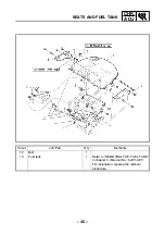
Page 52: ... AND FUEL TANK in chapter 3 Manual No 5JW1 AE1 Fuel Drain 1 Fuel tank side panel left and right 1 1 2 Bolt 2 3 Nut 1 4 Fuel sender coupler 1 5 Fuel pump coupler 1 6 Fuel tank overflow hose 1 7 Fuel tank breather hose 1 8 Hose holder 1 9 Fuel hose holder 2 10 Fuel hose 1 Refer to REMOVING THE FUEL TANK and INSTALLING THE FUEL HOSE in chapter 3 Manual No 5JW1 AE1 11 Fuel return hose 1 ...

Page 53: ... 45 CHK ADJ SEATS AND FUEL TANK Order Job Part Q ty Remarks 12 Bolt 1 13 Fuel tank 1 Refer to REMOVING THE FUEL TANK in chapter 3 Manual No 5JW1 AE1 For installation reverse the removal procedure ...

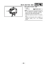
Page 54: ...stallation surfaces of the fuel tank when installing the fuel pump Always use a new fuel pump gasket Install the fuel pump as shown in the illustra tion Tighten the fuel pump bolts in stages in a crisscross pattern and to the specified torque FWD T R 4 Nm 0 4 m kg SEATS AND FUEL TANK ...

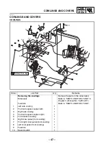
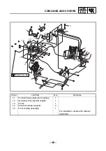
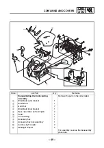
Page 55: ...r listed Rider seat Refer to SEATS AND FUEL TANK in chapter 3 Manual No 5JW1 AE1 Fuel tank Refer to SEATS AND FUEL TANK 1 Left side cowling 1 2 Front turn signal coupler left 1 3 Right side cowling 1 4 Front turn signal coupler right 1 5 Front bottom cowling 1 6 Right inner panel front cowling 1 7 Front right inner panel front cowling 1 8 Left inner panel front cowling 1 9 Fuse box 1 10 Hazard swi...

Page 56: ...1 0 m kg 2 13 Order Job Part Q ty Remarks 11 Front left inner panel front cowling 1 12 Accessory box solenoid coupler 1 13 Clamp 1 14 Sub wire harness coupler 3 15 Front cowling assembly 1 For installation reverse the removal procedure COWLINGS AND COVERS ...

Page 57: ...the order listed 1 Windshield outer bracket 1 2 Windshield 1 3 Grommet 7 4 Windshield inner bracket 1 5 Rear view mirror left and right 2 6 Panel 1 7 Front cowling 1 8 Accessory box 1 9 Accessory box lock assembly 1 0 Auxiliary light coupler 2 A Headlight coupler 2 For assembly reverse the disassembly procedure COWLINGS AND COVERS ...

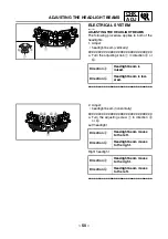
Page 58: ...ion a Headlight beam is raised Direction b Headlight beam is low ered a b 1 1 1 2 Adjust headlight beam horizontally a Turn the adjusting screw 1 in direction a or b Left headlight Right headlight Direction a Headlight beam moves to the left Direction b Headlight beam moves to the right Direction a Headlight beam moves to the right Direction b Headlight beam moves to the left b a 1 b a ADJUSTING T...

Page 59: ...Place the motorcycle on a suitable stand so that the front wheel is elevated 1 Reflector 2 For AUS only 2 Brake caliper left and right 2 Refer to REMOVING INSTALLING THE FRONT WHEEL in chap ter 4 Manual No 5JW1 AE1 3 Wheel axle pinch bolt 1 Loosen 4 Front wheel axle 1 5 Front wheel 1 6 Collar left 1 7 Collar right 1 8 Brake disc left and right 2 For installation reverse the removal procedure ...

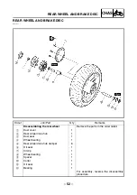
Page 60: ...assembling the rear wheel Remove the parts in the order listed 1 Dust cover 1 2 Rear wheel drive hub 1 3 Dust seal 1 4 Wheel bearing 1 5 Rear wheel drive hub damper 6 6 Oil seal 1 7 Circlip 1 8 Wheel bearing 1 9 Spacer 1 0 Collar 1 A Oil seal 1 B Bearing 1 For assembly reverse the disassembly procedure ...

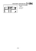
Page 61: ... 53 CHAS INSTALLING THE BEARING 1 Install bearing 1 a 3 5 4 5 mm b rear wheel a b 1 REAR WHEEL AND BRAKE DISC ...

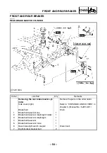
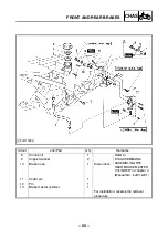
Page 62: ...ove the parts in the order listed Side cover right Refer to COWLINGS AND COVERS in chapter 3 Manual No 5JW1 AE1 Brake fluid Drain 1 Brake fluid reservoir cap 1 2 Brake fluid reservoir diaphragm holder 1 3 Brake fluid reservoir diaphragm 1 4 Brake fluid reservoir 1 5 Brake fluid reservoir hose 1 6 Rear brake light switch coupler 1 Disconnect 7 Right footrest bracket bolt 2 ...

Page 63: ...Remarks 8 Union bolt 1 Refer to DISASSEMBLING ASSEMBLING THE REAR BRAKE MASTER CYLINDER in chapter 4 Manual No 5JW1 AE1 9 Copper washer 2 10 Brake hose 1 Disconnect 11 Cotter pin 1 12 Pin 1 13 Brake master cylinder 1 For installation reverse the removal procedure ...

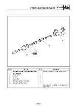
Page 64: ... Disassembling the rear brake mas ter cylinder Remove the parts in the order listed 1 Dust boot 1 2 Circlip 1 3 Push rod 1 4 Brake master cylinder kit 1 5 Brake master cylinder 1 For assembly reverse the disassembly procedure FRONT AND REAR BRAKES ...

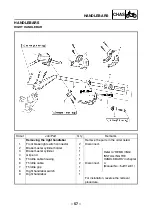
Page 65: ...tch connector 2 Disconnect 2 Brake master cylinder holder 1 Refer to REMOVING INSTALLING THE HANDLEBARS in chapter 4 Manual No 5JW1 AE1 3 Brake master cylinder 1 4 Grip end 1 5 Throttle cable housing 1 6 Throttle cable 2 Disconnect 7 Throttle grip 1 8 Right handlebar switch 1 9 Right handlebar 1 For installation reverse the removal procedure HANDLEBARS ...

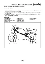
Page 66: ... to help maintain the basic maneuverability of the motorcycle 3 The hydraulic unit which is the main component of the ABS is centrally located on the motorcy cle to increase mass centralization ABS layout 1 ABS warning light 2 Fail safe relay 3 Electronic control unit ECU 4 Hydraulic unit 5 Rear disc rotor 6 Rear wheel sensor 7 Rear brake caliper 8 Front brake caliper 9 Front wheel sensor 0 Front ...

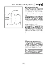
Page 67: ...tly EAS00873 Useful terms Wheel speed The rotation speed of the front and rear wheels Chassis speed The speed of the chassis When the brakes are applied wheel speed and chassis speed are reduced However the chassis travels forward by its inertia even though the wheel speed is reduced Brake force The force applied by braking to reduce the wheel speed Wheel lock A condition that occurs when the rota...

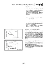
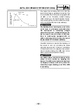
Page 68: ...s reduced Slip occurs between the tire and the road surface and brake force is gener ated The limit of this brake force is determined by the friction force between the tire and the road surface and is closely related to wheel slippage Wheel slippage is represented by the slip ratio Therefore side force is also closely related to wheel slippage See figure È If the brakes are applied while keeping t...

Page 69: ...cy to lock If the slip is large and the wheel has a ten dency to lock point A in the figure the ECU ABS reduces the brake fluid pressure in the brake caliper and increases the pressure of the brake fluid in the brake caliper when the tendency to lock has diminished point B in the figure Motorcycle speed Wheel speed Pressurized Depressurized Brake force EAS00876 ABS operation and motorcycle control...

Page 70: ...he tires Even in motorcycles equipped with an ABS overturning of the motorcycle cannot be prevented if it is braked suddenly The ABS functions to prevent the tendency of the wheel to lock by controlling the brake hydraulic pressure But if there is a tendency of the wheel to lock on a slippery road surface due to engine braking the ABS may not be able to prevent the wheel from locking WARNING _ The...

Page 71: ...ws normal braking even if the ABS is not operating properly When this occurs the ABS warning light on the meter assembly comes on The ABS stores the malfunction codes in the memory of the ECU ABS for easy problem identifica tion and troubleshooting ABS block diagram 1 Rear brake master cylinder 2 Hydraulic unit 3 Hydraulic pump 4 ABS motor 5 Buffer chamber 6 Hydraulic control valve 7 Front brake m...

Page 72: ...elec tromotive force is generated in the wheel sen sors Wheel rotation speed is detected based on the frequency of this alternating voltage 3 At high speed 4 At low speed 5 Wheel sensor 6 Sensor rotor 1 2 2 1 ABS warning light The ABS warning light comes on to warn the rider if a malfunction in the ABS occurs When the main switch is set to ON the ABS warning light comes on for 2 seconds to check i...

Page 73: ...e hydraulic unit adjusts the front and rear wheel brake fluid pressure to control the wheel rota tion speed according to signals transmitted from the ECU ABS 1 1 1 To rear brake master cylinder 2 Hydraulic pump 3 ABS motor 4 Buffer chamber 5 Hydraulic control valve 6 To front brake master cylinder 7 To the rear brake caliper 8 To the ECU ABS 9 To the front brake caliper ANTI LOCK BRAKE SYSTEM FJR1...

Page 74: ...rake caliper is open 2 When the ABS is activated the solenoid valve 2 is opened by the power supplied from the ECU ABS signals to decrease the brake fluid pressure and the spool 3 of the flow control valve is moved toward the solenoid valve 3 When the ECU ABS stops transmitting signals to decrease the brake fluid pres sure the solenoid valve 2 closes and the brake fluid is pressurized again Pressu...

Page 75: ...e the ABS is operating 1 Buffer chamber pressurized 2 Buffer chamber depressurized 3 Raised piston Electronic control unit ECU The ECU ABS 1 controls the ABS and is installed under the tray bracket To protect the ECU ABS from water damage it is protected by a cover 2 ANTI LOCK BRAKE SYSTEM FJR1300A ...

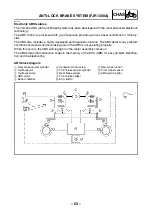
Page 76: ... Front wheel sensor 9 Rear wheel sensor 0 Main fuse A Main switch B Generator C Rectifier regulator D ABS fuse E ABS motor fuse F ABS test coupler G ECU ABS H Rear brake light switch I Front brake light switch J Tail brake light K Meter assembly L ABS warning light M Fail safe relay N ABS motor relay O Solenoid relay P Hydraulic unit Q ABS motor R Front solenoid S Rear solenoid The necessary actio...

Page 77: ...on code is stored in the memory of the ECU ABS for easy problem identification and troubleshoot ing NOTE _ Some types of failures are not recorded in the memory of the ECU ABS e g a drop in bat tery voltage 1 Software operation flow 2 Set the main switch to ON 3 Initialize 4 Self diagnosis when static 5 Self diagnosis when riding 6 Receive signals 7 Control operation 8 Depressurize pressurize È 8 ...

Page 78: ...ivated and it becomes impossible for the solenoid valve to reduce the hydraulic pressure of the brake fluid and normal braking is resumed The ABS motor relay is also activated by signals transmitted from the ECU ABS and operates simultaneously when the ABS starts to reduce the hydraulic pressure of the brake fluid If the solenoid relay is turned off the motor relay is also deactivated and the moto...

Page 79: ...aster cyl inder increases and the brake fluid is sent to the brake caliper via port A and port B At this time the inlet and outlet check valves of the pump close the lines and brake fluid is not sent As a result the brake master cylinder directly pressurizes the brake caliper during normal braking When the brake lever is released the brake fluid in the brake caliper returns to the brake master cyl...

Page 80: ...ke fluid is sent to the brake caliper via port C C and port D A and the buffer chamber As a result the hydraulic pressure in the brake caliper is reduced The brake fluid stored in the buffer chamber is pumped back to the brake master cylinder by the fluid pressure pump linked to the pump motor 1 Brake master cyl inder 2 Brake light switch 3 ABS motor 4 Pump 5 Buffer chamber 6 Flow control valve 7 ...

Page 81: ...rs via port A 7 and port C C At this time the brake is pressurized at a constant speed regardless of the brake fluid pressure level since restriction of port A 7 changes so that a constant pressure difference is maintained between chamber A J and cham ber B K of the flow control valve 1 Brake master cyl inder 2 Brake light switch 3 ABS motor 4 Pump 5 Buffer chamber 6 Flow control valve 7 Port A 8 ...

Page 82: ...rning light comes on while riding a malfunction has been detected in the ABS The ABS hydraulic control will not be performed The ABS will have recourse to manual braking if this occurs 3 The ABS warning light flashes while riding If the ABS warning light flashes while riding there is no problem with the function of the ABS However the ECU ABS input has unstable factors For details refer to TROUBLE...

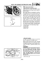
Page 83: ...pin test coupler can be accessed by removing the right inner panel front cowl ing When the test coupler adaptor is connected to the 4 pin test coupler the ABS warning light starts flashing and the multifunction display indicates all the malfunction codes recorded in the ECU ABS NOTE _ The ABS warning light comes on or flashes if the motorcycle is ridden with the test coupler adaptor connected to t...

Page 84: ...torcycle is maintained ABS function A brake system in which the hydraulic control has been performed by the ABS alerts a rider that the wheels had a tendency to lock by generating a reaction force pulsating action in the brake lever or brake pedal When the ABS is activated the grip between the road surface and tires is close to the limit The ABS cannot prevent wheel lock on slippery surfaces such ...

Page 85: ...rake hose hydraulic unit to front brake caliper 5 Front wheel sensor 6 Front wheel sensor rotor 7 ABS test coupler 8 Electronic control unit ECU 9 Rear brake hose rear brake master cylinder to hydraulic unit 0 Fail safe relay A Hydraulic unit B Rear brake hose hydraulic unit to rear brake caliper C Rear wheel sensor rotor D Rear wheel sensor 4 5 6 9 A C D B 1 0 8 7 3 2 ...

Page 86: ... R P W G R W B R L G W B4 B5 Sb R W Y Lg Br W L W W1 W B P W B3 W2 B1 W R B2 Front wheel sensor coupler Wire har ness end ABS test coupler Fail safe relay cou pler Hydraulic unit coupler Rear wheel sensor cou pler Meter assembly coupler Sub wire harness ABS coupler ECU ABS coupler Wire har ness end Wire harness end Wire har ness end Wire har ness end Wire har ness end Wire har ness end Wire harnes...

Page 87: ... BLACK O W B BLACK Y G B L Br R R W Br Br R GRAY R L L B L B L B R L L B D GRAY R L G B G B G B R LG B D GRAY R L R B R B R B R L R B D GRAY R B R G B2 Br R R W G W Y L G L G R Lg Y L Ch W Dg BLACK BLUE BLUE BLUE L G B B B Gy W BB1 BB2 BB4 BB3 B B B B R W R B L W G Y Br B R W R B W L G Y Br B B W R L B R L Y Br W L W B1 Lg Sb B2 W1 G R Lg Sb B1 B2 W1 G R R G R W R B W W R R Y Br W L W C P B Lg Sb ...

Page 88: ...7 Main fuse 8 ABS motor fuse 9 Battery Sub wire harness ABS ECU ABS Rear wheel sensor _ Fail safe relay a Hydraulic unit b ABS test coupler c Front wheel sensor k ABS warning light l Multifunction meter ß Rear brake light switch Front brake light switch À Start switch ...

Page 89: ... ABS warning light flashes ABS operation is normal The brake switch is defective or improperly adjusted The rear wheel is racing The motorcycle is continuously ridden on extremely uneven roads 2 Self diagnosis and service The ECU ABS has an ABS self diagnostic function By utilizing this function quick problem identification and service are possible The malfunction codes are stored in the memory of...

Page 90: ...e troubleshooting A ABS malfunction check using the ABS warning light B Detailed ABS malfunction check The results of the self diagnosis by the ECU ABS are displayed using the multifunction display or a pocket tester C Determining the cause and location of the malfunction Determine the cause of the malfunction from the condition and place where the malfunction occurred D ABS maintenance Execute th...

Page 91: ... malfunction code number and record it YES NO NO Check the fuse C 2 All indicator lights do not come on C 3 Warning light flashes continu ously C 5 Diagnose by malfunction codes C 4 ABS warning light flashes every 0 5 second Check the connectors and couplers Check the brake switch circuit Check the ECU ABS connector Check the wire har nesses C 1 Only ABS warn ing light does not come on Check the t...

Page 92: ...heck the test coupler located in the right inner panel front cowling Is the T C terminal grounded 1 Yes Disconnect the grounding lead from the T C terminal and install the protective cap onto the test coupler NOTE _ When the test coupler adaptor is connected to test coupler the T C terminal is grounded 2 No C 3 Function of the test coupler terminals The ABS self diagnostic function of the ECU ABS ...

Page 93: ...1 Indicate the malfunction code Example malfunction code 14 2 ABS warning light flashes every 0 5 second for more than 6 seconds C 4 C 5 If the ABS warning light flashes every 0 5 second the malfunction code of a past malfunction has not been stored in the memory of the ECU ABS If a malfunction code is displayed on the multi function display the ABS warning light flashes Make sure that the custome...

Page 94: ...ction code as follows Set the pocket tester range to DC 20 V Connect the pocket tester negative probe to the T F termi nal light green of the test coupler adaptor and the pocket tester positive probe to the positive bat tery terminal Figure É Determine the malfunction code according to the movement of the pocket tester needle Figure Ê A tester reading with the digits of 10 and digits of 1 pattern ...

Page 95: ...not come on the ABS warning light lead may be disconnected or the contact of the ABS warning light may be defective 3 Remove the ECU ABS coupler and check the ECU ABS coupler and test coupler adaptor ends of the white red lead for continuity Refer to ABS COUPLERS If there is continuity the ECU ABS is defective Replace the ECU ABS Refer to D 1 Maintenance of the ECU ABS If there is no continuity th...

Page 96: ...ng are probable causes to explain why the ABS warning light flashed while riding and then stopped flashing or stopped flashing when the main switch was set to OFF then to ON 1 The rear wheel was rotated with the motorcycle on the centerstand The system is normal 2 The rear wheel raced The system is normal 3 The motorcycle was ridden on the rear wheel with the front wheel elevated The system is nor...

Page 97: ...rear 14 wheel sensor 13 14 Wheel sensor installation Wheel sensor housings Wheel sensor rotors C 5 3 Mal function codes 13 front wheel and 14 rear wheel page 92 15 front 16 rear No continuity in the front or rear wheel sensor circuits 15 16 Continuity of sensor circuits ABS wire harness circuit Connection of sensor coupler C 5 4 Mal function codes 15 front wheel sensor and 16 rear wheel sensor pag...

Page 98: ...itted from the ECU ABS to release the hydraulic state when the battery voltage is nor mal Brake dragging Hydraulic unit operation test 2 Refer to D 6 3 2 Rear wheel brake line C 5 11 Mal function code 42 page 96 51 Front wheel will not recover from the locking tendency even though the signal is continuously transmitted from the ECU ABS to release the hydraulic state when the battery voltage is low...

Page 99: ...oseness distortion and bends C 5 2 Malfunction code 12 Rear wheel sensor signal is not received correctly Set the main switch to OFF then back to ON 1 ABS warning light remains on Defective connection in the rear wheel sensor circuit Rear wheel sensor coupler is disconnected D 4 Rear wheel sensor lead or coil is broken D 4 Sub wire harness ABS sensor circuit is disconnected Refer to CIRCUIT DIAGRA...

Page 100: ...ircuit is detected Front or rear wheel sensor coupler is broken D 3 4 Front or rear wheel sensor or lead is broken D 3 4 Sub wire harness ABS sensor circuit is broken Refer to CIRCUIT DIAGRAM Sub wire harness ABS is disconnected from the ECU ABS coupler terminal D 1 NOTE _ Check that both the front and rear wheel sensor couplers are connected securely If the motorcycle is ridden after malfunction ...

Page 101: ...for continuity 4 Fail safe relay Check if the fail safe relay operates correctly D 2 5 Wire harness Check for continuity between the red blue terminal of the fail safe relay coupler and the positive battery terminal Remove the ABS fuse and check for continuity between the brown white lead of the fail safe relay coupler and the ABS fuse See the illustration below C 5 7 Malfunction code 32 Fail safe...

Page 102: ...nd then check for continuity between the white black lead terminals and the red white lead terminals C 5 9 Malfunction code 34 ABS motor operation malfunction is detected ABS motor keeps rotating and does not stop Check the following 1 ABS motor Check if the ABS motor coupler located in the right side cover is connected properly Check the ABS motor for continuity D 5 2 Sub wire harness ABS Remove ...

Page 103: ...ose lines 4 Brake hose lines Check the brake hose lines for kinks and deterioration WARNING _ Only use genuine Yamaha parts Using other brake pipes hoses and union bolts may close the brake hose lines Check that the connections of the brake hose lines from the brake master cylinder to the hydrau lic unit and to the front brake caliper from the hydraulic unit are correct WARNING _ The front brake w...

Page 104: ...is no brake drag on the rear wheel and make sure it rotates smoothly Check for brake disc distortion 2 Brake master cylinder and brake caliper Check that the brake fluid pressure is correctly transmitted to the brake disc when the brake pedal is operated and that the pressure decreases when the pedal is released 3 Brake fluid Visually check the brake fluid in the brake master cylinder reservoir an...

Page 105: ...he final check in D 6 is performed If the front and rear brake hose connections are reversed on the hydraulic unit the pulsating action in the brake lever and brake pedal will be performed in the reverse order when the final check in D 6 is performed 5 Hydraulic unit solenoid coupler terminal Check if the front and rear hydraulic unit solenoid coupler terminals hydraulic unit and sub wire harness ...

Page 106: ...tion of the front wheel Refer to C 5 10 Malfunction code 41 2 Brake master cylinder and brake caliper Refer to C 5 10 Malfunction code 41 3 Brake fluid Refer to C 5 10 Malfunction code 41 4 Brake hose lines Refer to C 5 10 Malfunction code 41 5 Hydraulic unit solenoid coupler terminals Refer to C 5 10 Malfunction code 41 6 Hydraulic unit Refer to C 5 10 Malfunction code 41 7 Battery voltage Measur...

Page 107: ...tion of the rear wheel Refer to C 5 11 Malfunction code 42 2 Brake master cylinder and brake caliper Refer to C 5 11 Malfunction code 42 3 Brake fluid Refer to C 5 11 Malfunction code 42 4 Brake hose lines Refer to C 5 11 Malfunction code 42 5 Hydraulic unit solenoid coupler terminals Refer to C 5 11 Malfunction code 42 6 Hydraulic unit Refer to C 5 11 Malfunction code 42 7 Battery voltage Measure...

Page 108: ... filter case Refer to AIR FILTER CASE in chapter 3 Manual No 5JW1 AE1 1 ABS motor coupler 1 Disconnect 2 Hydraulic unit solenoid coupler 1 Disconnect 3 Fail safe relay 1 4 Fail safe relay coupler 1 Disconnect 5 ECU ABS 1 6 Front wheel sensor coupler 1 Disconnect 7 ECU ABS coupler 3 Disconnect For installation reverse the removal procedure ANTI LOCK BRAKE SYSTEM FJR1300A ...

Page 109: ... Check ECU ABS terminals 1 Cracks damage Replace the ECU ABS ECU ABS coupler terminals 2 Defective connections contamination dis connections Repair or clean NOTE _ If the ECU ABS coupler terminals are clogged with mud or dirt clean with com pressed air D 2 Maintenance of the ABS fail safe relay Removing the fail safe relay 1 Remove ABS fail safe relay coupler 1 NOTE _ Do not pull the ABS fail safe...

Page 110: ...afe relay Connect the positive battery terminal to ter minal 7 and the negative battery terminal to terminal 8 and then check for continuity between terminals 4 and 5 of the solenoid relay Tester positive probe Terminal 4 Tester negative probe Terminal 5 Tester reading is Replace the fail safe relay CAUTION _ When connecting the solenoid relay and battery terminals be careful not to short circuit ...

Page 111: ...ive battery terminal to terminal 1 and then check for continuity between terminals 2 and 5 of the ABS motor relay Tester positive probe Terminal 2 Tester negative probe Terminal 5 Tester reading is Replace the fail safe relay CAUTION _ Be sure to connect the pocket tester posi tive and negative probes correctly If the pocket tester probes are connected in reverse the diode of the fail safe relay w...

Page 112: ...d NOTE Place the motorcycle on a suitable stand so that the front wheel is elevated Rider seat Refer to SEATS AND FUEL TANK in chapter 3 Manual No 5JW1 AE1 Fuel tank Refer to SEATS AND FUEL TANK 1 Reflector 2 For AUS only 2 Front wheel sensor coupler 1 Disconnect 3 Brake caliper left and right 2 Refer to Maintenance of the front wheel sensor and sensor rotor 4 Front wheel sensor 1 5 Wheel axle pin...

Page 113: ...m kg T R 40 Nm 4 0 m kg T R 30 Nm 3 0 m kg T R 23 Nm 2 3 m kg T R 72 Nm 7 2 m kg LS LT LT 6 6 4 Order Job Part Q ty Remarks 9 Collar right 1 10 Brake disc left and right 2 For installation reverse the removal procedure ANTI LOCK BRAKE SYSTEM FJR1300A ...

Page 114: ... Do not attempt to disassemble it If faulty replace with a new one Removing the front wheel sensor 1 Remove brake hose holder 1 front wheel sensor lead holder 2 brake caliper 3 front wheel sensor 4 CAUTION _ Be sure not to contact the sensor elec trode to any metal part when removing the front wheel sensor from the sensor housing Do not operate the brake lever when removing the brake caliper Check...

Page 115: ...mbly NOTE The wheel sensor rotor of the motorcycle is inserted under pressure by a special process and cannot be replaced as a single unit To replace the sensor rotor replace the wheel assembly Regulated resistance 1 12 1 68 kΩ at 20 C Installing the front wheel sensor 1 Install front wheel NOTE _ Align the slot in the sensor housing with the projection of the front fork before assembly CAUTION _ ...

Page 116: ...nt wheel sensor check the wheel sensor lead for twists and the sensor electrode for foreign materials CAUTION _ To route the front wheel sensor lead refer to CABLE ROUTING 3 Check front wheel sensor installation Check if the wheel sensor housing is installed properly Refer to D 3 Mainte nance of the front wheel sensor and sensor rotor T R 30 Nm 3 0 m kg T R 40 Nm 4 0 m kg ...

Page 117: ...listed NOTE Place the motorcycle on a suitable stand so that the rear wheel is elevated ECU ABS Refer to ECU ABS AND FAIL SAFE RELAY 1 Rear wheel sensor coupler 1 Disconnect 2 Rear wheel sensor 1 3 Brake torque rod nut bolt 1 1 Refer to INSTALLING THE REAR WHEEL in chapter 4 Manual No 5JW1 AE1 4 Wheel axle nut 1 5 Wheel axle pinch bolt 1 Loosen 6 Wheel axle 1 7 Brake caliper 1 8 Rear wheel 1 ...

Page 118: ... 110 CHAS ANTI LOCK BRAKE SYSTEM FJR1300A Order Job Part Q ty Remarks 9 Sensor housing 1 10 Brake disc 1 For installation reverse the removal procedure ...

Page 119: ...ot operate the brake lever when removing the brake caliper Removing the rear wheel sensor 1 Disconnect rear wheel sensor 1 2 Remove clamp 2 rear wheel sensor lead holder 3 3 Remove rear wheel sensor 1 CAUTION Be sure not to contact the sensor electrode to any metal part when removing the rear wheel sensor from the sensor housing Checking the rear wheel sensor and sen sor rotor Refer to Checking th...

Page 120: ...aterials cause damage to the inner sensor rotor and rear wheel sensor 2 Install rear wheel sensor 1 NOTE _ When installing the rear wheel sensor check the rear wheel sensor lead for twists and the sensor electrode for foreign materials CAUTION _ To route the rear wheel sensor lead refer to CABLE ROUTING 3 Connect rear wheel sensor coupler 1 rear wheel sensor lead holder 2 clamp 3 CAUTION _ To rout...

Page 121: ... in the order listed Air filter case Refer to AIR FILTER CASE in chapter 3 Manual No 5JW1 AE1 ABS motor coupler Hydraulic unit sole noid coupler 1 1 Refer to ECU ABS AND FAIL SAFE RELAY Fail safe relay Fail safe relay coupler 1 1 Brake fluid Drain 1 Union bolt copper washers 1 2 2 Front brake hose 1 front brake master cylinder to hydraulic unit 3 Union bolt copper washers 1 2 4 Front brake hose 1 ...

Page 122: ...10 New New New New Order Job Part Q ty Remarks 6 Rear brake hose 1 rear brake master cylinder to hydraulic unit 7 Union bolt copper washers 1 2 8 Rear brake hose 1 hydraulic unit to rear brake caliper 9 Nut 2 10 Breather hose 1 11 Hydraulic unit 1 12 Hydraulic unit bracket 1 1 13 Hydraulic unit bracket 2 1 For assembly reverse the disassembly procedure ...

Page 123: ... Keep them away from dirt and do not sub ject them to shocks The ABS wheel sensor cannot be disas sembled Do not attempt to disassemble it If faulty replace with a new one Do not set the main switch to ON when removing the hydraulic unit Do not clean with compressed air Do not reuse the brake fluid Brake fluid may damage painted surfaces and plastic parts Therefore always clean up any spilt brake ...

Page 124: ...Out of specification Replace the hydrau lic unit 2 Measure resistance of the solenoid valve rear Connect the pocket tester Ω 1 to the ter minals of solenoid valve rear Tester positive probe Terminal 4 Tester negative probe Terminal 3 Out of specification Replace the hydrau lic unit 3 Check ABS motor for continuity Connect the pocket tester Ω 1 to the ter minals of the ABS motor coupler Tester posi...

Page 125: ...es CAUTION _ When removing the brake hoses cover the area around the hydraulic unit to catch any spilt brake fluid Do not allow the brake fluid to contact other parts 2 Remove hydraulic unit bracket 1 1 NOTE Loosen the nuts in the proper sequence 3 Remove hydraulic unit 1 NOTE _ To avoid brake fluid leakage and to prevent foreign materials from entering the hydraulic unit insert a rubber plug a or...

Page 126: ...ubber plugs or bolts M10 1 25 installed in the union bolt holes before installing the hydraulic unit 3 Remove rubber plugs or bolts M10 1 25 4 Install copper washer brake hose 1 to the rear brake caliper brake hose 2 from the rear brake master cylinder brake hose 3 to the front brake caliper brake hose 4 from the front brake master cylinder union bolt WARNING _ The brake hoses to the front and rea...

Page 127: ...the brake lever and the brake pedal response Refer to D 6 3 1 Hydraulic unit operation test 1 CAUTION _ Always check the operation of the hydrau lic unit according to the brake lever and the brake pedal response 8 Delete the malfunction codes Refer to D 6 4 Deleting the malfunction codes 9 Perform a trial run Refer to D 6 5 Trial run Recommended brake fluid DOT 4 ...

Page 128: ...ed the brake system when the brake related parts are removed CAUTION _ Bleed the brake system in the following order 1st Front brake caliper a 2nd Rear brake caliper b Brake lever 1 Brake pedal 2 Front brake hose 3 from the front brake master cylinder Rear brake hose 4 from the rear brake master cylinder 2 b a 1 4 3 ...

Page 129: ...the brake fluid level is very low brake operation is faulty NOTE Be careful not to spill any brake fluid or allow the brake master cylinder reservoir or brake fluid reservoir to overflow When bleeding the ABS make sure there is always enough brake fluid before applying the brake Ignoring this precaution could allow air to enter the ABS considerably lengthening the bleeding procedure If bleeding is...

Page 130: ...ss the brake pedal and hold it in posi tion g Loosen the bleed screw NOTE Loosening the bleed screw will release the pressure and cause the brake lever to contact the throttle grip or the brake pedal to fully extend h Tighten the bleed screw and then release the brake lever or brake pedal i Repeat steps e to h until all of the air bubbles have disappeared from the brake fluid in the plastic hose j...

Page 131: ...inder reservoirs 2 Check the wheel sensors for proper installa tion 3 Perform hydraulic unit operation test 1 or 2 4 Delete the malfunction codes 5 Perform a trial run D 6 1 Checking the brake fluid level of the brake master cylinder reservoirs 1 Check brake fluid level Refer to CHECKING THE BRAKE FLUID LEVEL in chapter 3 Manual No 5JW1 AE1 D 6 2 Checking the wheel sensors for proper installation ...

Page 132: ... unit operation can be tested by the following two methods Hydraulic unit operation test 1 this test gen erates the same reaction force pulsating action that is generated in the brake lever and brake pedal when the ABS is activated Hydraulic unit operation test 2 this test checks the function of the ABS after the system was disassembled adjusted or ser viced D 6 3 1 Hydraulic unit operation test 1...

Page 133: ... V the ABS warning light comes on and the ABS does not operate Battery voltage Higher than 12 8 V 5 Connect the test coupler adaptor 1 to the test coupler 2 Test coupler adaptor 90890 03149 6 Set the engine stop switch 1 to 7 Set the main switch to ON NOTE After setting the main switch to ON wait approximately 2 seconds until the ABS warn ing light goes off 1 8 Push the start switch 1 for at least...

Page 134: ... after and continues for approximately 1 second NOTE Be sure to continue to operate the brake lever and brake pedal even after the pulsating action has stopped 11 After the pulsating action has stopped in the brake pedal it is generated in the brake lever 0 5 second after and continues for approximately 1 second CAUTION _ Check that the pulsating action is felt in the brake lever brake pedal and a...

Page 135: ...stand 2 Set the main switch to OFF 3 Remove right inner panel front cowling front right inner panel front cowling Refer to COWLINGS AND COVERS 4 Check battery voltage Lower than 12 8 V Charge or replace the battery NOTE _ If the battery voltage is lower than 12 8 V charge the battery and perform hydraulic unit operation test 2 If the battery voltage is lower than 10 V the ABS warning light comes o...

Page 136: ...ition again CAUTION _ Check that the brake lever returns to its home position before the brake pedal returns to its home position If the brake pedal returns to its home position before the brake lever does check that the brake hoses are connected correctly to the hydraulic unit If either the brake lever or brake pedal returns to its home position slowly check that the brake hoses are connected cor...

Page 137: ...omes on for 2 seconds goes off for 3 seconds then starts flashing to confirm that all malfunction codes are deleted 8 Set the main switch to OFF 9 Disconnect the test coupler adaptor from the test coupler and install the protective cap onto the test coupler NOTE _ Do not forget to install the protective cap onto the test coupler CAUTION _ Since the malfunction codes remain in the memory of the ECU...

Page 138: ...nect the pocket tester Ω 1 to the ECU coupler and start switch coupler Tester positive probe blue white 1 ECU Tester negative probe white blue 2 start switch No continuity Replace or repair the wire harness Battery voltage Higher than 12 8 V 1 2 Br W B2 B1 B3 W1 W2 Lg L W P W W B W R R W R B W L G Y Br B 2 1 7 Check ECU voltage Connect the pocket tester DC 12 V to the ECU coupler Tester positive p...

Page 139: ...d drive unit 2 Battery 3 Starter relay 4 Fuel injection system fuse 5 Front brake switch 6 Clutch switch 7 Fuse box 8 Radiator fan motor 9 Wire harness 0 Neutral switch A Sidestand switch B Oil level switch C Rear brake switch D Horn E Ignition coil F Main fuse G ABS motor fuse FJR1300A ...

Page 140: ...e cut off switch 6 Hydraulic unit FJR1300A 7 Fail safe relay FJR1300A 8 ECU engine 9 ECU ABS FJR1300A 0 Starting circuit cut off relay A Speed sensor B Cylinder identification sensor C O2 sensor D Crankshaft position sensor E Accessory box solenoid F Headlight relay 1 G Headlight relay 2 H Fuel injection system relay I Turn signal relay J Radiator fan motor relay ...

Page 141: ...ITY in chapter 8 Manual No 5JW1 AE1 Damage wear Repair or replace Improperly connected Properly connect Incorrect continuity reading Replace the switch R W R B L W B R Y Y R Y L B B P Lg B Sb UP DOWN DgBr W Ch OFF BROWN Sb Sb Dg Ch Dg Ch Br W Br W ON OFF BLUE B B G Y Br BLUE R W R B L W G Y Br B L Y B Y B Y L Y BLACK BLACK P B Lg Sb Br W L B Ch Dg B Y Y R Y L Y ON OFF P R Br L Br R Br LBr R R B B ...

Page 142: ...5 Dimmer switch 6 Horn switch 7 Windshield position switch 8 Turn signal switch 9 Front brake light switch 0 Engine stop switch A Start switch B Rear brake light switch C Neutral switch D Sidestand switch E Oil level switch F Hazard switch G Fuse CHECKING THE SWITCHES ...

Page 143: ...R LG B D GRAY R L R B R B R B R L R B D GRAY R B R G B2 Br R R W G W Y L G L G R Lg Y L Ch W Dg BLACK BLUE BLUE BLUE L G B B B Gy W BB1 BB2 BB4 BB3 B B B B R W R B L W G Y Br B R W R B W L G Y Br B B W R L B R L Y Br W L W B1 Lg Sb B2 W1 G R Lg Sb B1 B2 W1 G R R G R W R B W W R R Y Br W L W C P B Lg Sb Br W L B Ch Dg B Y Y R Y L Y B Ch Dg B P B Sb Lg Br W G B Ch Dg B Y Y R Y B R B R B Y Br R W R W...

Page 144: ...rd key for driving See caution below NOTE Each standard key is registered during production therefore re registering at purchase is not neces sary CAUTION DO NOT LOSE THE CODE RE REGISTERING KEY If the code re registering key is lost reg istering new codes in the standard keys is impossible The standard keys can still be used to start the vehicle however if code re registering is required i e if a...

Page 145: ... unit After replacement of the immobilizer unit or ECU 1 Turn ON the main switch with the code re registering key Make sure the immobilizer system indicator light goes on for about one second and then off This shows that the code re registering key registration is finished 2 Check that the engine can be started 3 Consequently carry out the standard key registration according the section below Repl...

Page 146: ...the standby mode ends 2 After the main switch is turned ON with the code re registering key before 5 seconds elapses turn OFF the main switch and then turn ON the main switch with the standard key the first new key that you want to register 3 It enters the key registration mode and the two standard key codes that have been stored in the memory are erased and the first new standard key code will be...

Page 147: ...istration disables the lost standard key because its key code has been changed Standard key registration method less than 5 0 s less than 5 0 s less than 5 0 s less than 5 0 s Registration of the second unregis tered standard key is complete Second standard key Code re regis tering key First standard key Registration mode Blinking ends when the registration of the sec ond unregistered standard key...

Page 148: ...m from the tran sponder of other vehi cle 2 Register the standard key 53 IMMOBILIZER UNIT Cannot transmit code between the ECU and immo bilizer unit Noise interference or discon nected lead cable 1 Obstruction due to radio wave noise 2 Error by disconnection of the communication harness 3 Immobilizer unit failure 4 ECU failure 1 Check the wire har ness and connector 2 Replace the immobi lizer unit...

Page 149: ...ckup fuses for continuity Refer to CHECKING THE FUSES in chapter 3 Manual No 5JW1 AE1 Are the main ignition and backup fuses OK Replace the fuse s 2 Battery Check the condition of the battery Refer to CHECKING AND CHARGING THE BATTERY in chapter 3 Manual No 5JW1 AE1 Open circuit voltage 12 8 V or more at 20 C Is the battery OK Clean the battery terminals Recharge or replace the battery 3 Main swit...

Page 150: ...reen 1 Tester negative probe black 2 2 1 R G B2 Br R R W G W Y L G L G R Lg Y L Ch W Dg B BB Y L G L R W R G R G B2 R W Lg Y L B 2 1 Set the main switch to ON Measure the voltage 12 V between red green and black on the immobilizer unit coupler Is the voltage within specification The wiring circuit from the battery to the immobilizer unit is faulty and must be repaired 3 Voltage Connect the pocket ...

Page 151: ...e 1 Tester negative probe black 2 Set the main switch to ON Measure the voltage 12 V between green blue and black on the immobilizer unit coupler Is the voltage within specification The wiring circuit from the immobilizer unit to the meter assembly is faulty and must be repaired Replace the immobi lizer unit B BB Y L G L R W R G R G B2 R W Lg Y L B 2 1 ...

Page 152: ...ect Set the main switch to ON with the code re registering key and check the immobilizer system indicator Malfunction Second standard key transpon der is defective Correct Re register the stan dard key Malfunc tion Replace the standard key Check if a self diagnosis code is dis played Displayed Read the malfunction code and check the corresponding part Refer to SELF DIAGNOSIS ERROR CODE INDICATION ...

Page 153: ...Y R L G B G B G B R LG B D GRAY R L R B R B R B R L R B D GRAY R B R G B2 Br R R W G W Y L G L G R Lg Y L Ch W Dg BLACK BLUE BLUE BLUE L G B B B Gy W BB1 BB2 BB4 BB3 B B B B R W R B L W G Y Br B R W R B W L G Y Br B B W R L B R L Y Br W L W B1 Lg Sb B2 W1 G R Lg Sb B1 B2 W1 G R R G R W R B W W R R Y Br W L W C P B Lg Sb Br W L B Ch Dg B Y Y R Y L Y B Ch Dg B P B Sb Lg Br W G B Ch Dg B Y Y R Y B R ...

Page 154: ...per ate Pocket tester 90890 03112 1 Main and signaling system fuses Check the main and signaling system fuses for continuity Refer to CHECKING THE FUSES in chapter 3 Manual No 5JW1 AE1 Are the main and signaling system fuses OK Replace the fuse s 2 Battery Check the condition of the battery Refer to CHECKING AND CHARGING THE BATTERY in chapter 3 Manual No 5JW1 AE1 Minimum open circuit voltage 12 8...

Page 155: ...Sb W Sb W Br Br O W 1 2 4 3 6 Accessory box solenoid Remove the accessory box solenoid cou pler from the wire harness Connect the pocket tester Ω 1 to the accessory box system solenoid terminal as shown Tester positive probe orange white 1 Tester negative probe black 2 Measure the accessory box solenoid resis tance Accessory box solenoid resis tance 19 21 Ω at 20 C Is the accessory box solenoid OK...

Page 156: ...b wire harness ABS Defective connection of the main switch coupler Defective connection of the meter coupler ABS WARNING LIGHT CONTINUES TO FLASH Defective brake light switch front or rear Disconnected brake light switch front or rear coupler Disconnected wire harness Blown damaged or incorrect fuse main fuse Defective connection of the sub wire harness ABS and the wire harness couplers ABS WARNIN...

Page 157: ...urn signal indicator light q Meter light r Oil level switch s Left handlebar switch t Clutch switch u Pass switch v Dimmer switch w Windshield position switch x Turn signal switch y Horn switch z Horn Front turn signal light left Front turn signal light right Hazard switch Headlight relay 1 å Headlight relay 2 ç Headlight assembly Auxiliary light Headlight Taillight assembly Tail brake light Rear ...

Page 158: ...itch k Pass switch l Dimmer switch m Windshield position switch n Turn signal switch o Horn switch p Horn q Front turn signal light left r Front turn signal light right s Hazard switch t Headlight relay 1 u Headlight relay 2 v Headlight assembly w Auxiliary light x Headlight y Taillight assembly z Tail brake light Rear turn signal light left Rear turn signal light right Rear brake light switch Tur...

Page 159: ......

Page 160: ...YAMAHA MOTOR CO LTD 2500 SHINGAI IWATA SHIZUOKA JAPAN ...

Page 161: ...LACK Y G B L Br R R W Br Br R GRAY R L L B L B L B R L L B D GRAY R L G B G B G B R LG B D GRAY R L R B R B R B R LR B D GRAY R B R G B2 Br R R W G W Y L G L G R Lg Y L Ch W Dg BLACK BLUE BLUE BLUE L G B B B Br B B B Gy W BB1 BB2 BB4 BB3 B B B B R W R B L W G Y Br B R W R B W L G Y Br B B W R L B R L Y Br W L W B1 Lg Sb B2 W1 G R Lg Sb B1 B2 W1 G R R G R W R B W W R R Y Br W L W L B Br G C B L P W...

Page 162: ... L B L O O L R L R L D B L B L E W L B1 BB B2 B2 B L W B W B W B E P W P W B L Gy B L Y L B L Gy G Gy G Gy G W L Y B L L W B B L W L Y B L L W Y B L L Y B L BLACK DARK GREEN L B L P W P W B L L BLACK L L P B L P B L L BLACK O W B BLACK Y G B L Br R R W Br Br R GRAY R L L B L B L B R L L B D GRAY R L G B G B G B R LG B D GRAY R L R B R B R B R LR B D GRAY R B R G B2 Br R R W G W Y L G L Lg Y L Ch W...

Reviews: