background image


2


3. Preparations before Operation 

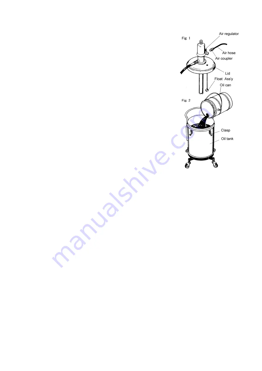
3.1 Setting the Hose 

1)  Install the attached oil-proof hose and the grip meter at the oil discharge 

port of the pump, and clamp the connecting portion securely. 

2)  Connect the attached air chuck to the air hose and fix it with a hose band. 

(The air hose is separately available.) If the air chuck to be connected to 
the compressor is not available, purchase it separately. (Fig. 1) 


3.2 Setting Oil 

1)  Release the 3 clasps on the top of the oil tank, and the lid can be removed 

together with the pump Assy. 

2)  Supply new oil in the oil tank. (Fig. 2) 


<NOTE>


Take extreme care not to allow sand and dust to adhere on the suction 
tube and float of the pump. 

 
3)  Put the lid on the oil tank as it was and fix the oil tank and the lid with the 3 

clasps. 


3.3 Operating the equipment 

1)  Turn the knob of the air regulator counterclockwise to reset the indicator of the pressure gauge to “0”. After that, 

connect the air chuck to supply air. 


<NOTE>


Using an air regulator permits adjusting the supply air pressure to the pump and reducing unnecessary pump 
motion, thereby improving the work efficiency and extending the life of the pump.   
When the knob of the air regulator is turned clockwise, the air pressure will be increased (the indicator of the 
pressure gauge gradually goes from “0” to a larger number). When the knob is turned counterclockwise, the air 
pressure will be reduced (the indicator of the pressure gauge goes back to “0”). 

 
2)  As the knob of the air regulator is gradually turned clockwise, the will be started when the supply pressure is 0.2 or 

0.3 MPa. 

3)  The pump is operated for a while and then stops when the hose is filled with oil. If the gun lever is pulled in this 

status, the oil lubricator can be used any time. 

4)  Set the supply air pressure to 0.5 to 0.7 MPa. 

Summary of Contents for SGR-110A5

Page 1: ...IL LUBRICATOR SGR 110A5 MODEL No 880635 WARNING Prior to operating this pump be sure to read this operation manual for safety After reading the manual please keep it at hand any time for your quick re...

Page 2: ......

Page 3: ...nd caution symbols have the meanings described below Be sure to remember their meanings WARNING This indicates the existence of potential hazard which if not avoided will result in death or serious in...

Page 4: ...Any secondary accident such as pollution of installation due to hose damage or leakage from the valve without shutting off the supply air shall be attributable to the user s responsibility During mach...

Page 5: ...hine 3 5 Maintenance and Inspection 5 1 Troubleshooting and Corrective Measures 4 5 2 Maintenance and Inspection 5 6 Disassembly and Assembly 6 1 Disassembling the Air Motor and the Lower Pump 5 6 2 D...

Page 6: ...a lower pump to draw up the material as shown in the figure at right When compressed air is supplied from the compressor to the air motor the air piston starts its up down motion by the function of t...

Page 7: ...ent 1 Turn the knob of the air regulator counterclockwise to reset the indicator of the pressure gauge to 0 After that connect the air chuck to supply air NOTE Using an air regulator permits adjusting...

Page 8: ...rtant machine 1 Before starting oil supply be sure to turn the knob of the grip meter counterclockwise to reset to the 0 position If the short needle has not been reset turn the long needle to reset t...

Page 9: ...any open valve on the material output side Check if the material does not leak at the exhaust port of the air motor The air motor is faulty Ask for servicing the air motor When the outlet side is clo...

Page 10: ...ed directly so its failure rate is very low The air motor does not need to be disassembled If disassembling is required ask the dealer to disassemble the air motor WARNING Gasoline is a high volatilit...

Page 11: ...any blemish or wear is found replace the part with a new one 5 Do not disassemble the housing and the connecting rod if possible If they are disassembled assemble them so that the clearance between t...

Page 12: ...late 1 9 710927 Valve seat 1 10 712018 Cylinder 1 11 683503 Nut 1 12 710912 Valve seat 1 13 712168 Collar 1 14 712175 Adapter 1 15 611101 Bolt 1 No Parts No Description Q ty 1 851755 Pump Assy 1 2 682...

Page 13: ...006 Spacer 15 59310 001 Totalizer Assembly 16 55212 115 Screw Totalizer Frame 17 59008 001 Packing Gland Kit Buna N 18 13268 000 Cam Standard electronic 19 22872 001 Quad Ring Buna N 20 58959 001 Scr...

Page 14: ...elow 480 480 953 SGR 110A5 880635 5 x 1 FLUID CONNECTION DISCHARGE PORT Grip meter AIR CONNECTION SUPPLY PORT Coupler plug PS 20PM 0 3 0 7 MPa 87 5 dB ENV TEMPERATURE 0 60 C MATERIAL TEMP 0 80 C 27 5...

Page 15: ...cause corrosion inflation or dissolution of the component parts of the product 4 Irregularity arising from repair made by other than by our firm our regional office dealer or authorized service perso...

Page 16: ...Hengelo O The Netherlands PHONE 31 0 74 242 2032 FAX 31 0 74 242 1055 Manufactured by YAMADA CORPORATION INTERNATIONAL DEPARTMENT No 1 3 1 Chome Minami Magome Ohta Ku Tokyo 143 8504 Japan PHONE 81 0 3...

Reviews: