background image

10

An ASSA ABLOY Group brand

P/N AYRD210-INST-FUL Rev B


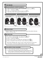
Lock Operation

1

Enter current Master PIN code,  
followed by the


key.

   1

Enter '1' to change Master PIN code, 
followed by the 


key. 

   2

Enter the new Master PIN code (4~8 
digits), followed by the


key.  

   3

1.  Enter the 8-digit default Master PIN code (12345678) followed by the   key. 
2.  Enter “1” followed by the   key. 
3.  Enter new 4-8 digit Master PIN code followed by the   key. 

   Change Default Master Code Before Programming*

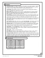
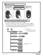
User Codes can only be programmed through the Master Code.
1. Enter the 4-8 digit Master PIN code followed by the   key. 
2. Enter “2“ followed by the   key. 
3. Enter the User number to be registered (1-25) followed by the   key. 
4. Enter a 4-8 digit PIN code for the User number followed by the   key. 

   Set Up User Codes

Note: When registering User codes, the code must be entered with in 20 seconds. 
If time expires, no codes are registered and the process must be re-started.

    PIN code structure

Maximum number of user codes is 250 with Network Module; without Network Module, 
maximum is 25 user codes.

ƒ

ƒ

LockoutƒisƒaƒMenuƒfeatureƒthatƒrestrictsƒPinƒcodeƒaccessƒ(exceptƒMaster).

ƒ

ƒ

Privacyƒmodeƒisƒsetƒbyƒpressingƒandƒholdingƒtheƒbuttonƒ(foundƒbelowƒthumbƒturn)ƒforƒaƒ
durationƒofƒfourƒbeeps.ƒThisƒdeactivatesƒtheƒkeypadƒandƒsound,ƒandƒbecauseƒitƒisƒsetƒfromƒ
theƒinside,ƒprovidesƒaƒsecureƒandƒsilentƒlockƒforƒtheƒconvenienceƒofƒtheƒoccupant(s).ƒ


    Privacy Mode vs. All Code Lockout Mode


*Default Master PIN Code must be changed prior to programming the lock.

Summary of Contents for YRD210

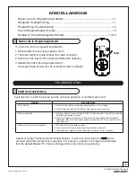
Page 1: ...able on our website in printed Spanish and French Go to www yalerealliving com Click Product Information Documentation and then Installation Instructions Este documento está disponible en español en nuestra página de internet Vaya a www yalerealliving com Presione Información del Producto y Documentación y luego Instrucciones de Instalación Ce document est disponible sur notre site Web dans le fra...

Page 2: ... or modifications to this unit will void the the warranty FCC FCC ID U4A YRHCPZW0 Z Wave U4A YRHCPZB0 Zigbee Model s YRD210 YRD220 YRT210 or YRT220 This equipment has been tested and found to comply with the limits for a Class B digital device pursuant to Part 15 of the FCC Rules These limits are designed to provide reasonable protection against harmful interference in a residential installation T...

Page 3: ...oved for the transmitter by Industry Canada To reduce potential radio interference to other users the antenna type and its gain should be so chosen that the equivalent isotropically radiated power e i r p is not more than that necessary for successful communication Section 7 1 3 of RSS GEN This Device complies with Industry Canada License exempt RSS standard s Operation is subject to the following...

Page 4: ...eded Quick Start Guide Installation Instructions Door Marker Outside Escutcheon Bolt Strike Plate Screw Pack Keys Included in the box COMPONENTS AND TOOLS Inside Escutcheon Inside Mounting Plate Battery Cover 4 AA Alkaline Batteries INSTALLATION Outside Escutcheon Inside Escutcheon 4 AA Alkaline Batteries 2 Through bolts 4 screws Keys Battery Cover Bolt Strike Plate Inside Mounting Plate 3 Mountin...

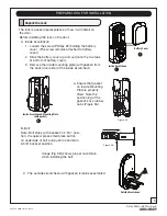
Page 5: ...ove the inside mounting plate with gasket from the back door side of the inside escutcheon Battery Cover Inside Escutcheon C The outside escutcheon with gasket remains assembled B Bolt Note Bolt ships with backset in 2 3 4 posi tion If required press small black button on underside of bolt and push to shorten to 2 3 8 backset position Inside Escutcheon Mounting Plate with gasket Outside Escutcheon...

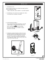
Page 6: ... cable through 2 1 8 diameter hole Figure 3A NOTE Cable goes under bolt and through Ensure that the tailpiece is oriented correctly see arrows Fig 3B INSTALL LOCK Figure 4B Figure 4A Figure 3B Figure 3A Tongue 4 Holding the outside escutcheon flush to the door position the inside mounting plate by first routing the cable and connector through the mounting plate s 1 2 hole Fig 4A and then inserting...

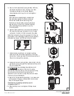
Page 7: ... is not smooth review the previous steps to ensure proper installation 9 Insert four 4 AA alkaline batteries Lock responds with a series of beeps red blue flash and a quick flash of all keypad LEDs Note Refer to programming instructions prior to completion of step 10 10 Install battery cover and tighten Phillips head screw 6 Attach cable assembly to the inside escutcheon PC board by lining up notc...

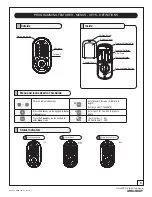
Page 8: ...vacy Mode Button Menu and Icons Used in This Guide Cylinder Click the indicated number Enter Master PIN code 4 8 digits in length Factory default 12345678 Press the Star key on the keypad to Enter or Accept entry Enter User PIN Can be 4 8 digits in length Press the Pound key on the keypad to enter Menu mode User Number 1 25 RF Controlled 1 250 M U Low Battery Warning 1 Lock out Mode 2 Return to pr...

Page 9: ...lt is retracted electronically activating the keypad will extend the bolt during Auto Re Lock duration or when Auto Re Lock is disabled Shutdown Time The unit will shutdown for a default of sixty 60 seconds and not allow operation after the wrong code entry limit has been met When the unit is in Shutdown the Status Indicator flashes RED and BLUE the keypad flashes as well Audio Mode Choosing Disab...

Page 10: ...egistered 1 25 followed by the key 4 Enter a 4 8 digit PIN code for the User number followed by the key Set Up User Codes Note When registering User codes the code must be entered with in 20 seconds If time expires no codes are registered and the process must be re started PIN code structure Maximum number of user codes is 250 with Network Module without Network Module maximum is 25 user codes Loc...

Page 11: ...terface PC or hand held device to en sure communication between the lock and the controller unit Master PIN Setting M M User PIN Deletion Audio Mode All Code Lock out HCP Module Setting Enable Enable Register Disable Delete Disable User Number UN 1 25 without network module 1 250 with network module 1 2 User PIN Registration Complete U Complete Auto Re lock 7 Enable Disable This function appears o...

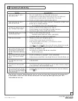
Page 12: ...the reset button and wait while the lock tests bolt operation For security purposes it is highly recommended that the default Master Pin Code be changed before any other programming Reset Button Symptom Suggested Action Door is binding a Check that door and frame are properly aligned and door is free swinging b Check hinges They should not be loose or have excessive wear on knuckles Bolt will not ...

Page 13: ... Disable Auto Re lock Mode to lock the door automatically If low battery indicator is lit see below change batteries PIN codes will not register PIN codes must consist of 4 to 8 digits to register The same PIN code cannot be used for multiple users Registration management of PIN codes is set at the authority of Master Contact the Master user User codes must be entered within 20 seconds or the proc...

Page 14: ... from cylinder Note position of ring flange in relation to cylinder How to Replace or Install Cylinder 2 5 8 66 5 For 6 pin cylinders 1 3 8 thick doors 2 7 8 73 For 6 pin cylinders 1 3 4 thick doors ONLY 1 3 16 30 For 6 pin cylinders 1 3 8 thick doors 1 7 16 36 5 For 6 pin cylinders 1 3 4 thick doors ONLY CAUTION The cylinders furnished for use in 1 3 8 doors have a tailpiece that is 1 4 shorter t...

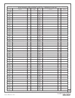
Page 15: ...o Network Module Up to 25 Users Location Door Number User User Name User PIN Code User Type User Name User PIN Code Master User 13 User 1 User 14 User 2 User 15 User 3 User 16 User 4 User 17 User 5 User 18 User 6 User 19 User 7 User 20 User 8 User 21 User 9 User 22 User 10 User 23 User 11 User 24 User 12 User 25 ...

Page 16: ...er ___ User ___ User ___ User ___ User ___ User ___ User ___ User ___ User ___ User ___ User ___ User ___ User ___ User ___ User ___ User ___ User ___ User ___ User ___ User ___ User ___ User ___ User ___ User ___ User ___ User ___ User ___ User ___ User ___ User ___ User ___ User ___ User ___ User ___ User ___ User ___ User ___ User ___ User ___ User ___ User ___ User ___ User ___ User ___ User _...

Page 17: ...ale Security Inc an ASSA ABLOY Group company Yale is a registered trademark of Yale Security Inc an ASSA ABLOY Group company All rights reserved Yale Real Living is a trademark of Yale Security Inc an ASSA ABLOY Group company Copyright 2011 Yale Security Inc an ASSA ABLOY Group company All rights reserved Reproduction in whole or in part without express written permission of Yale Security Inc an A...

Reviews: