8.8 MAINTENANCE OF MOTOR
Motor
Under normal conditions the motor is practically maintenance-
free.
Spring activated disc brake
Service to the motor brake is reduced to checking and
adjustment of the nominal brake air gap. The disc brake air gap
should be between 0.15 and 0.6mm (see Tab. 5). This
guarantees short reaction time and low noise emission. When
the wear of the brake lining comes down to the point where the
maximum possible air gap has finally been reached, the brake
lining has to be replaced.
Attention:
Do not allow the brake friction pads to come into
contact with lubricant or similar contaminants.
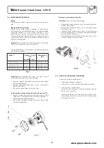
The table below shows the dimensions of the brake air gap that
have to be maintained:
Attention:
When checking the air gap, the motor must be
switched off and the hoist must be unloaded.
• Measure air gap SLu between armature disc and magnet
part with feeler gauge.
• Compare measured air gap value with max. admissible air
gap SLu (see Tab. 5).
• If necessary, replace rotor with brake lining.
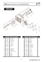
Replacement of brake rotor with friction lining (Fig. 17):
• Loosen the three countersunk socket screws (item 3), lift-off
flange (item 2) and replace rotor with friction lining (item 1).
• Reassemble in opposite sequence.
• Finally, check the brake function with nominal load in lifting
and lowering operation.
Yale
Electric Chain Hoist - CPV/F
®
13
www.yaleproducts.com
Model
Air gap + 0.1 SLu Motor brake
mm type
nominal max.
CPV/F 2-8, 5-4 0.15 0.3 BFK457 - 05
CPV/F 5-8, 10-4 0.2 0.4 BFK457 - 06
CPV/F 10-8, 20-4 0.2 0.6 BFK457 - 08
Tab. 5
Fig. 17
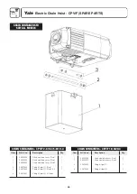
Build-up of motor brake (Fig. 18):
Attention:
The unit must be de-energised!
• Disassemble the control cover (item 2) by loosening the four
cylinder screws (item 1).
• Remove the transformer (item 3) by unscrewing the four
crosshead screws.
• Loosen the four socket screws (item 4) of the brake and
pull-off the brake (item 5). Disconnect the control cable from
the circuit board if necessary.
• After replacement of the motor brake, make sure that the
function is tested with nominal load.
Fig. 18
8.9 ELECTRIC CHAIN HOIST IN GENERAL
In particular, check the following parts:
• Threaded connections in general.
Check all nuts, screws and locking devices for tightness.
• Chain container - material type.
Ensure the chain container is securely fastened. Check for
tears or wear in the fabric.
Connection between hoist and suspension bracket resp.
trolley. Check for cracks or wear. Ensure all safety devices
are in place and secure.
Yale
CPV/F
®


