Table 1. Instruments and Controls (See Figure 5) (Continued)
Item
No.
Item
Function
2
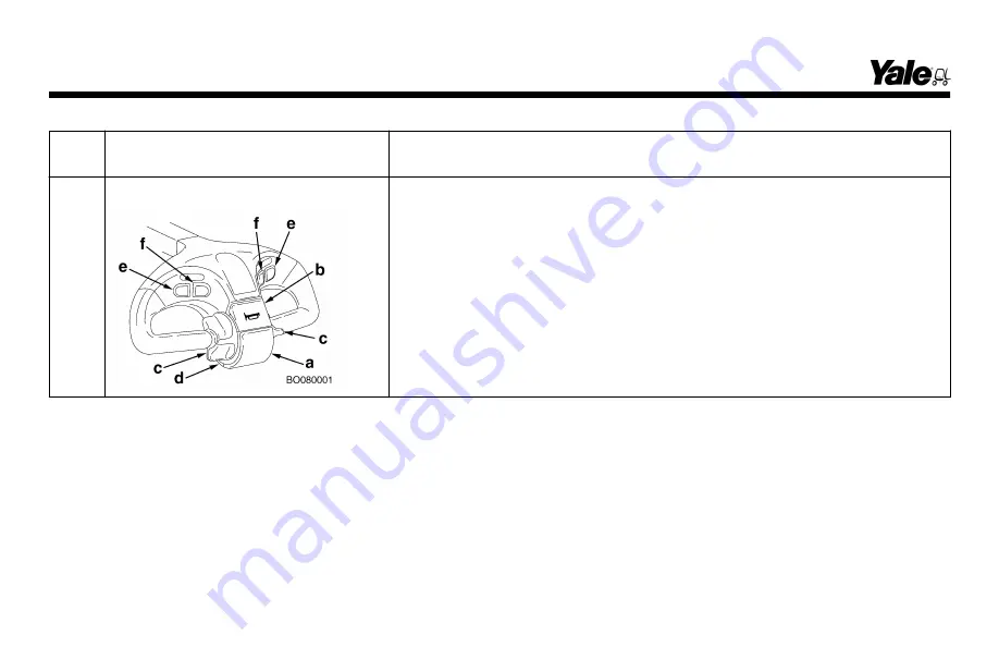
Control Head Assembly
The control handle assembly has the following controls:
(a) Traction Reverse button
(b) Horn button
(c) Direction and speed control
(d) Slow speed button
(e) Lower button
(f) Lift button
NOTE:
Operation of these controls is described in the following paragraphs.
Model Description
18
Summary of Contents for A245
Page 13: ...Figure 4 Warning and Safety Labels Model Description 11 ...
Page 15: ...Instruments and Controls Figure 5 Instruments and Controls Model Description 13 ...
Page 50: ...Figure 9 Putting the Lift Truck on Blocks Maintenance Schedule Maintenance Schedule 48 ...
Page 51: ...Figure 10 Maintenance Points Maintenance Schedule 49 ...
Page 63: ...1 LED 2 LABEL Figure 14 Charger LED s Maintenance 61 ...
Page 70: ...Figure 18 Battery Compartment Maintenance 68 ...
Page 74: ...NOTES 72 ...


