4
Installation
07.2020
69
ba
-o
.2
.6
.0
-us
-3
.2
-ys
|
A1
18
67
50
1 Re
v A
E
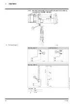
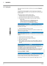
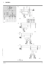
Assembly position 5
Dimension [in]
d
3.58
e
4.84
The arrow in the figure shows the contact area.
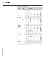
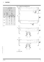
Type
Trolley type
Reeving
Drum length
Assembly
position
YKA/SKA
OE-S04
2PS, 4PS
L2 + L3
1
YKB/SKB
OE-S04
2PS, 4PS
L2 + L3 + L4
1
YKC/SKC
OE-S05
2PS, 4PS
L2 + L3 + L4
1
OE-S06
YKE/SKE
OE-S06
2PS
L2 + L3 + L4 + L5
2
1)
OE-S07
4PS
L2 + L3 + L4 + L5
4
YKD/SKD
OE-S06
2PS
L2
3
1)
L3 + L4 + L5
5
4PS
L2 + L3 + L4 + L5
3
1)
1)
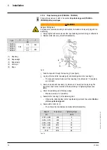
Observe the assembly position of the screws.
Observe the mounting position of the screws.
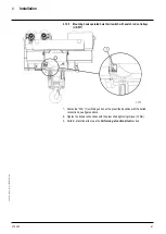
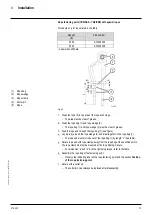
Fasten the “
PL
S” (1) switching unit on at the prescribed position with the bolted
connections, see figures above.
Tighten the bolted connections with the prescribed tightening torque (12 Nm).
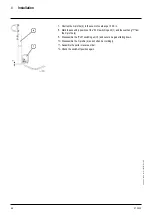
Perform a functional test, see the
Performing a functional test
section
Perform the functional test
Move the operational limit switch (B
) to the top.
–
Movement stops.
Actuate the override button “S260” on the control box and the UP button at the same
time until the hoisting movement stops.
–
No more upward movement is possible.
Actuate the DOWN button.
–
If a downwards movement is possible, the “PLS”
switching unit has tripped.
–
If no downwards movement is possible, then the emergency limit switch has
tripped. In this case the “PLS” switching unit must be adjusted anew.


