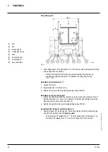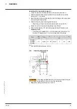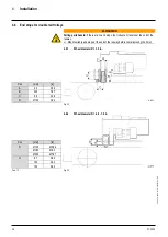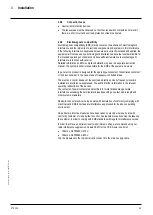
4
Installation
07.2020
39
ba
-o
.2
.6
.0
-us
-3
.2
-ys
|
A1
18
67
50
1 Re
v A
E
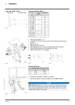
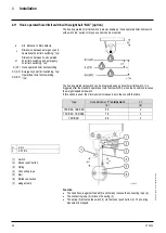
Trolley types OE-S06 - OE-S07
Trolley types OE-S06 - OE-S07
Hook position
Eccentric position
X
Hook
position
Eccentric
[in]
1.5...1.59
1
A
1.61...1.79
C
1.81...1.99
2
A
2.01...2.19
C
2.2...2.38
3
A
2.4...2.58
C
2.6...2.78
4
A
2.8...2.97
C
2.99...3.17
5
A
3.19...3.37
C
3.39...3.56
6
A
3.58...3.76
C
Fig. 31
Fig. 32
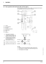
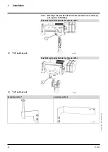
•
Unscrew fixing elements (1 + 2)
•
On OE-S07 4PD, the pieces of two units are supplied loose (please unscrew as
required).
•
Remove hook (3)
•
Rotate hook by180° (OE-S04)
•
Insert adjusting screws (S) in the hook position determined from the table.
•
Position eccentric plates (4) in slot as specified by the table.
•
Tighten fixing elements (1 + 2) finger-tight.
Fig. 33 Fig. 34
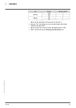
Horizontal adjustment:
Fig. 35
Pos
OE-S04 -OE-S05 OE-S06 - OE-S07
[in]
[in]
Z
≥
0.39
≥
0.59
Y
≥
1.18
≥
1.18
1.
Adjust final hook position according to Fig. and table.
2.
Tighten fixing elements (1) and (2) with tightening torque
M10 = 38 lb
f
ft
.
NOTICE
Malfunction hazard.
In the event of a fault, e.g. trolley running into the runway end
stops unchecked, broken rope, all elements of the anti-jump catch must be checked
immediately for damage/faults and completely replaced if necessary. The functional
reliability of the system must be ensured.


