


4
Installation
28
07.2020
ba
-o
.2
.6
.0
-us
-3
.2
-ys
|
A1
18
67
50
1 Re
v A
E
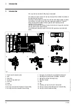
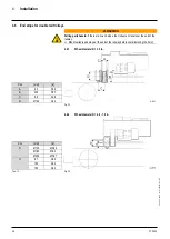
Preparatory work
(1) Nut
(2) Nut
(3) Threaded bolt
(4) Trolley side cheek
(5) Nuts
(6) Connection part
(7) Connecting pin
(8) Axle holder side
Fig. 14
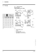
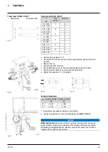
Check
flange width “B” and dimension “c” on the basis of Tab. 9 and adjust the trolley
to the beam width if necessary.
–
Observe here that the connection part (square-section tube) (6) must be
positioned centrally (to dimension “c”) between the trolley side cheeks
(“e1”
=
“e2”).
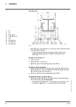
Adjustment work, dimension “c”:
Loosen the nut (2).
Adjust dimension “c” with the nut (1).
Tighten the nut (2) to the prescribed tightening torque 159 lb
f
ft.
Adjustment work, connection part:
Loosen the nuts (5) and slide the connection part (6) on the connecting pin (7) such
that the dimensions “e1” and “e2” are equal on the left and right between the trolley
side cheeks (4) and the connection piece (6).
Tighten the nuts (5) to the prescribed tightening torque 159 lb
f
ft.
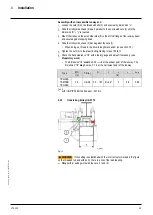
Assembly with a freely accessible runway end
Slide the trolley onto the runway end, check track clearance f/2 with a feeler gauge
and adjust if necessary (see
Preparatory work
).
–
The dimension “f/2”
must
be 0.02
+0.04
in at the widest point of the runway. The
dimension “f/2”
may
be max. 0.1 in at the narrowest point of the runway.


