background image

81

1.  Press the [FUNC] key.
2. 

Select  [EXTENSION  SETTING] → [SD 

CARD].

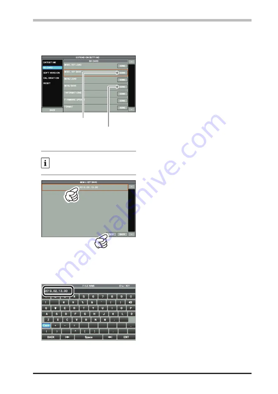
3.  Touch “DONE” for the data item to be saved.

Saving memory data

Save setting menu data

4.  To save the file with a new name, touch 

“NEW”.

To overwrite previously saved data, touch 
the file name, and touch “OK” when the 

overwrite confirmation screen appears.

Touch “CANCEL” to cancel overwrite save.

When overwriting

When saving with a new file name

Enter the file name (maximum 15 characters) 

on the file name input screen.

If the file name is not to be changed, proceed 

to step 6 as it is.

5.  Touch “ENT” to start saving data, or touch 

“BACK” to cancel the name input.

6.  “FILE SAVED” is displayed when data saving 

is completed.

7.  Touch the screen to end saving data.
8.  Press the [FUNC] key twice to return to the 

normal operation screen.

• 

Saving Memory data and Setting Menu data

The Memory Channel data, and the Setting Menu data can be saved to the SD Card:

Summary of Contents for FTDX101D

Page 1: ...EXT DISPLAY on page 13 or 17 Depending on the manual version Incorrect DVI I connector for connecting an external monitor Correct DVI D connector for connecting an external monitor Please use the DVI D connector to connect between the transceiver and the external monitor YAESU MUSEN CO LTD EH068H506 ...

Page 2: ...uency change at a predetermined frequency step MEM CH Selects the Desired memory channel GROUP Selects the memory group R FIL Pass band width selection of Roofing filter LEVEL Adjust the level of the 3DSS display How to assign functions to the MPVD ring 1 Press and hold the C S key The function selection screen is displayed 2 Touch the function you want to assign Functions can also be assigned in ...

Page 3: ...transmit audio input jack in the AM mode by pressing the MOX key Available Values MIC REAR Default Setting MIC Description MIC Audio is input from the MIC jack on the front panel REAR Disables the microphone circuit on the front panel and inputs audio data from the USB jack or RTTY DATA jack on the rear panel Change Setting Menu FM MOD SOURCE RADIO SETTING MODE FM FM MOD SOURCE Function Selects th...

Page 4: ...101MP 101D Operation Manual ...

Page 5: ......

Page 6: ...uching the Function Screen or by turning and pressing the MULTI knob are abbreviated to Select DISPLAY SETTING DISPLAY TFT DIMMER as described in the following Example How to adjust the brightness of the display 1 Press the FUNC key to display the function screen 2 Touch DISPLAY SETTING on the function screen or rotate the MULTI knob to select DISPLAY SETTING and then press the MULTI knob 3 Touch ...

Page 7: ...uency display 30 Inputting the Call Sign 30 Front Panel Controls Switches 32 Adjusts the VOX GAIN 33 Adjusts the VOX Delay Time 33 Adjusts the VOX anti trip sensitivity 33 QMB Channel Storage 35 QMB Channel Recall 35 Confirm the contents of QMB 35 Changing the number of QMB channels 35 Mark the operation band 35 Quick Split Operation 37 Direct input of offset frequency 37 Clarifier 39 RX Clarifier...

Page 8: ...amming on TFT Screen 71 Text Message Programming on FH 2 Remote Controller 71 Text Input 71 On The Air PSK Text Message Playback 71 Memory Operation 72 Memory Storage 72 Erasing Memory Channel Data 72 Check Memory Channel Status 73 Recall a Memory Channel other than 73 the last used VFO frequency 73 Memory Tune Operation 73 Moving Memory Data to the VFO register 74 Labeling Memories 74 Displaying ...

Page 9: ...uency band or the dual display that illustrates both the MAIN and SUB frequency bands The Hybrid Dual SDR Display presents two SDR outputs narrow band SDR and direct sampling SDR combined the same screen Since the display color of each SDR output can be changed the band re ceived by the narrow band SDR receiver can be viewed while also observing the condition of the entire band High brightness TFT...

Page 10: ...ent in the receiver passband the IF NOTCH feature can significant ly eliminate a narrow portion of the passband and remove the interfering signal Moreover when there are multiple interfering signals the DSP DNF Digital Notch Filter Automatic Tracking System can be effec tive even when an interfering frequency is changing ABI Active Band Indicator Band keys are arranged in a row at the top above th...

Page 11: ...es in consid eration of people who are fitted with medical devices such as heart pacemakers Electromagnetic waves from the device may af fect the medical device resulting in accidents caused by malfunctions Do not touch any liquid leaking from the liquid display with your bare hands There is a risk of chemical burns occurring when the liquid comes into contact with the skin or gets into the eyes I...

Page 12: ...oloration Do not place this device in a location where there is a lot of dust and humidity Doing so may result in fire and equipment failure Stay as far away from the antenna as possible during transmission Long term exposure to electromagnetic radiation may have a negative effect on the human body Do not wipe the case using thinner and ben zene etc Please use a soft and dry piece of cloth to wipe...

Page 13: ...le options Hand Microphone equivalent to the supplied microphone SSM 75G Reference Microphone M 1 Dual Element Microphone M 100 Ultra High Fidelity Desktop Microphone MD 200A8X Desktop Microphone MD 100A8X Lightweight Stereo Headphone YH 77STA External Speaker SP 101 External Automatic Antenna Tuner FC 40 Remote Control Keypad FH 2 Linear Amplifier AC Power Supply VL 1000 VP 1000 VL 1000Linear Amp...

Page 14: ... less Careful prepara tion of the antenna and or tuner will permit maximum performance and protect the transceiver from dam age High transmitter RF voltages may be present on the antenna install it so it will not be easily touched when in operation Antenna Connections Carefully follow the illustration regarding the proper connection of antennas and coaxial cables ANT 1 ANT 2 EXT SPKR KEY ACC TUNER...

Page 15: ...audio of MAIN band and SUB band will be output from the built in speaker of FPS 101 When connected to EXT SPKR terminal B audio of MAIN band is output from the built in speaker of FPS 101 and audio of SUB band is output from the speaker of the FTDX101MP DC Power Cable supplied Speaker Cable supplied Connected to the AC line outlet Connecting the DC power cable USA version only Connect the DC Power...

Page 16: ...the proper connection of the DC power cable Use the DC power cable supplied with the FTDX101D to make the power connections to the power sup ply ANT 1 ANT 2 EXT SPKR KEY ACC TUNER PTT METER GND LINEAR 13 8V REM EXT ALC RS 232C A B RED FUSE 25A Check the DC voltage and current rating 13 8 V 23 A of the power supply before connecting to the transceiver DC power cord supplied BLACK ...

Page 17: ...f TV FM antennas from Amateur transmitting antennas to the greatest extent pos sible Keep the transmitting coaxial cables separated from cables connected to home entertainment de vices Make sure to turn the transceiver OFF and disconnect all cables before moving the FTDX101MP or FPS 101 The AC Power Cord connected to a socket outlet with earthing connection A socket outlet with earthing connection...

Page 18: ...T ALC RS 232C A B SW1 5V SW2 FAST GND PTT MIC GND MIC φ6 3mm as viewed from front panel Remote Control Keypad FH 2 Key up voltage on the front key jack is approximately 3 3 V DC and key down current is approximately 1 mA Key up voltage on the rear key jack is approximately 5 0 V DC and key down current is approximately 3 mA ...

Page 19: ... ATT switch OFF may damage the VL 1000 Refer to the VL 1000 Operating Manual for details regarding amplifier operation Do not attempt to connect or disconnect coaxial cables when your hands are wet ANT 1 ANT 2 EXT SPKR KEY ACC TUNER PTT METER GND LINEAR 13 8V REM EXT ALC RS 232C A B DC IN LINEAR ALC 2 BAND DATA 2 CT 178 Connection Cable option HF 50MHz Antenna Coaxial Cable 50 ohm Connect to INPUT...

Page 20: ...D OUT pin pin 2 of the LINEAR jack This line is not compatible with negative DC voltages or AC voltages of any magnitude ANT 1 ANT 2 EXT SPKR KEY ACC TUNER PTT METER GND LINEAR 13 8V REM EXT ALC RS 232C A B DC IN LINEAR D sub 15 pin HF 50 MHz Antenna Antenna Cable 50 ohms GND GND RF OUT RF IN GND EXT ALC TX GND ANT 1 The figure above shows the FTDX101MP rear panel connections to other linear ampli...

Page 21: ...4 inch 3 contact jack accepts a CW key or keyer paddle A two contact plug cannot be used in this jack Key up voltage is 5 0 V DC and key down current is 3 mA KEY NC GND When connecting a single straight key DOT DASH COMMON When connecting an electronic keyer paddle AF OUT This 3 5 mm 3 contact jack provides dual channel low level receiver output for recording or external amplification The front pa...

Page 22: ...VL 1000 Solid state Linear Amplifier 13 5V OUT TX GND GND BAND DATA A BAND DATA B TX REQ NC NC EXT ALC GND BAND DATA C BAND DATA D TX INH GND NC ACC This 13 pin jack may be connected to an external device Power ON GND DATA1 DATA2 CLOCK CS 3 3V 13 8V Reserve Reserve CNT RX CNT TX Reserve IF OUT MAIN This RCA jack outputs the receiver 9 005 MHz IF signal This signal does not pass through the roof in...

Page 23: ... L DATA U SSB CW DIAL STEP page 103 5 10 Hz AM AM CH STEP page 103 2 5 5 9 10 12 5 25 kHz FM DATA FM FM CH STEP page 103 5 6 25 10 12 5 20 25 kHz MUTE Key While pressing the MUTE key the receiver audio from the speaker will be muted Microphone Speak into the microphone in a normal tone of voice with the microphone 5 cm away from the mouth P1 key Switches the operation to the MAIN band It is the sa...

Page 24: ...circuit Use the ROOFING FILTER Roofing filters attenuate strong signals that are outside of the de sired passband after converting to the 9MHz IF The roofing filter can attenuate unwanted frequency components Touch R FIL on the TFT screen to select the 3kHz filter for SSB the 1 2kHz filter or the 600Hz filter for CW An optional 300Hz filter is also available Included with FTDX101MP Use DSP interfe...

Page 25: ...fier drain current Standing Wave Ratio Final transistor temperature When the meter display screen is touched the transmit meter selection screen is shown the default default setting is PO on the left and ALC on the right PO PO COMP ALC ALC TEMP ID VDD SWR LEFT METER RIGHT METER AMC gain control display Displays compression level during speech processor operation Make adjustments with the PROC PITC...

Page 26: ...cy is displayed in red Keyboard Frequency Entry 1 Touch the Hz area of the frequency display 2 Enter the frequency using the numeric keys Clear all entered numbers The entered frequency is confirmed The display returns to the previous screen when back is touched Erases the rightmost digit If there is no operation within 10 seconds the input will be canceled 3 Touch ENT to confirm A short cut for f...

Page 27: ...ATT settings If the S meter fluctuates S 3 or more in the noise level or the received signal is extremely strong and it causes a high S meter indication 20dB or more activate the attenuator Since IPO does not only attenuate the incom ing signal but also improves the cross mod ulation characteristic try to activate the IPO first If the signal is still strong also use the ATT In this way you can att...

Page 28: ...istics can be individually set for each operating mode The basic objective of AGC is to maintain a constant audio output level once a certain minimum threshold of signal strength is achieved After touching AGC touch the desired time con stant AGC can be set for each operation band The AUTO selection mode selects the opti mum receiver recovery time for the reception mode Operating Mode AUTO AGC Sel...

Page 29: ...r and the receive frequency move to the touched position Press and hold the FAST key in the CENTER and CURSOR modes the Hz digit of the receive frequency will be 0 Press and hold the FAST key in FIX mode the receive frequency returns to the start frequency of the dis play area CENTER The receive frequency is always shown at the cen ter of the screen and spectrum display The band spectrum is shown ...

Page 30: ...ENT In FIX mode If the FAST key is held the receiver returns to the start frequency SPAN Set the frequency span display range of the scope screen After touching select the desired span The display level changes when SPAN is changed so reset the optimum display level with LEVEL each time 3DSS Switch between the 3DSS display and the waterfall display The display will change each time it is touched T...

Page 31: ... again to return to the original Normal Display Larger View HOLD Temporarily stops the operation of the Scope Dis play and the Filter Function Display Touch the dis play to enter HOLD state touch it again to restore Scope operation During HOLD HOLD flashes DISP Each time the key is pressed the Scope Screen Display changes as shown below Press the SUB key to adjust the SUB band refer ence level Onl...

Page 32: ... the Narrow Band SDR can be changed on the Color Selection Panel 1 Press the S MENU key to display the SCOPE MENU 2 Touch COLOR 3 Touch the desired color from the selections on the screen To change the color of the Narrow Band SDR touch and desired color block Favorite color combinations can be registered in the menu by pressing and holding M 1 M 2 or M 3 Even when the color is not changed the Nar...

Page 33: ...knob The following settings and operations can be performed with the MULTI control SPEED Set Scope Sweep Speed PEAK Adjust the Peak Signal Color Density MARKER ON OFF Marker indicates the transmit and receive frequency position within the Scope Display image COLOR Changes the scope display color LEVEL Adjust the reference level to make it eas ier to distinguish the scope display target signal from...

Page 34: ... AM N FM FM N DATA L DATA U DATA FM D FM N RTTY L RTTY U PSK Displays the selected radio emission type About TFT Displays FTDX101 series utilizes a TFT liquid crystal display Although TFT liquid crystal displays are made using very precise technology they are prone to develop dead pixels dark dot or pixels that are always on bright dot Please understand that such phenomena do not constitute produc...

Page 35: ...he FUNC key to save the new setting and exit the Setting Menu 6 Press the FUNC key to exit to normal operation Font setting for frequency display The height of the frequency display can be varied BOLD Default LIGHT 1 Press the FUNC key 2 Select DISPLAY SETTING DISPLAY FREQ STYLE 3 Select LIGHT or BOLD 4 Press the FUNC key to save the new setting and exit the Setting Menu 5 Press the FUNC key to ex...

Page 36: ...31 Note ...

Page 37: ...lting in a constant key down condition DOT DASH COMMON KEY NC GND Key up voltage is approximately 3 3 V DC and key down current is approximately 1 mA PHONES Jack Connect headphones to this standard ϕ6 3 stereo jack Inserting a headphone plug into this jack will deacti vate the internal and external speakers When wearing headphones we recommend that you turn the AF Gain levels down to their lowest ...

Page 38: ...g the transmitter to activate Adjusts the VOX Delay Time The Hang Time of the VOX system the trans mit receive delay after the cessation of speech may also be adjusted To set a different delay time 1 Press the FUNC key 2 Touch VOX DELAY 3 Rotate the MULTI knob while saying a brief syl lable like Ah and listening to the hang time for the desired delay Adjusts the VOX anti trip sensitivity The Anti ...

Page 39: ... er clockwise to reduce the drag or count er clockwise to increase the drag FAST Pressing this key will change the tuning of the MAIN Dial knob and MULTI knob When STEP DIAL function is assigned to a higher step rate In Spectrum Scope FIX mode a long press makes the receiver frequency the start fre quency with one touch When FINE TUNING is activated the amount of frequency change of the Main dial ...

Page 40: ...the FUNC key 2 Touch QMB LIST the QMB list will be dis played On the list display screen select the channel you want to delete and then touch DELETE to clear the selected QMB Changing the number of QMB channels The QMB channels can be changed from 5 chan nels or 10 channels 1 Press the FUNC key 2 Select OPERATION SETTING GENERAL QMB CH 3 Select 5ch or 10ch 4 Press the FUNC key to save the new sett...

Page 41: ...activated When transmitting the audio side tone when in CW operation is heard from the speaker 2 Press and hold the MONI key and adjust the Monitor level with the MULTI knob Transmit audio monitor is not activate in the FM DATA FM and D FM N modes If you are using the speaker for monitoring instead of headphones excessive advancement of the Monitor level can cause feedback to occur Additionally th...

Page 42: ... increase the SUB band transmis sion frequency by 5 kHz SYNC key The SYNC key can move the frequencies of the MAIN band and SUB band simultaneously Press and hold to adjust the SUB band frequency to the MAIN band frequency Quick Split Operation The Quick Split feature allows setting a one touch offset of 5 kHz as compared to the MAIN band fre quency to be applied to the transceiver SUB band transm...

Page 43: ...ressing the key below MPVD ring CLAR Clarifier VC TUNE MAIN SUB C S Costom Select key VC TUNE Operation key CLAR Acts as a clarifier knob VC TUNE Adjusts the tuning point when the VC tune function is activated C S 12 types of functions can be assigned in advance MAIN SUB Operates as a dial to set the frequency of the SUB band when the operation band is the MAIN band and as the frequency of the MAI...

Page 44: ... transmitter frequency can be set to the same frequency as the receiver 1 After offsetting the receiver frequency press the CLAR TX key The transmit frequency becomes the same as the receive frequency CLAR RX of the display changes to CLAR TRX 2 Press the CLAR TX key again only the recep tion frequency returns to the offset state CLAR TRX of the display changes to CLAR RX TX Clarifier The transmit...

Page 45: ...une operates the steep attenu ation characteristics of VC Tuner may cause some signals in the Spectrum Scope to be attenuated and disappear or the image may not appear uniform however this is not a malfunction The VC Tuning module in the FTDX101D is only for the MAIN band If you also want to use it on the SUB band of the FTDX101D please contact Yaesu The VC tune function works only with amateur ba...

Page 46: ... is pressed the transceiver will transmit on the SUB band fre quency To transmit at the MAIN band frequency press the MAIN band side TX key RX SUB band Press this key to activate receive on the SUB band frequency The LED inside the key will glow green when the transceiver is receiving on the SUB band frequency When pressed the SUB band received audio is MUTED and the indicator is turned OFF When m...

Page 47: ...erate in FM and DATA FM mode SQL The squelch system allows the back ground noise to be muted when no signal is being re ceived Normally the squelch is not used during SSB or CW operation Before operation set the operation of the RF SQL control to SQL The default setting is RF Rotate the RF SQL knob to adjust the squelch until the noise disappears If the squelch knob is turned too far to the right ...

Page 48: ...ob is turned the display will show the relative microphone gain or the keying speed for 1 2 second When pressed in SSB mode turns the AMC or speech processor ON OFF page 50 51 When pressed in CW mode the built in electronic keyer is turned ON OFF page 60 Outer Knob PROC PITCH In SSB mode adjusts the level of AMC or the Speech Processor 1 to 100 In CW mode adjusts the CW tone 300 Hz to 1050 Hz when...

Page 49: ...OPERATION SETTING GENERAL NB REJECTION 3 Rotate the MULTI knob to set the noise attenu ation 10dB 30dB 40dB 4 Press the FUNC key to save the new setting and exit the Setting Menu 5 Press the FUNC key to exit to normal operation Reduces longer duration pulse noise Reduces long duration noise as well as pulse noise 1 Press the FUNC key 2 Select OPERATION SETTING GENERAL NB WIDTH 3 Rotate the MULTI k...

Page 50: ...ce more If a very strong interfering carrier is encoun tered we recommend using the IF NOTCH filter first as it is the most effective notching tool in the receiver section NOTCH IF NOTCH Filter The IF NOTCH filter is a highly effective system that allows you to slice out an interfering beat note or other carrier signal from inside the receiver pass band The NOTCH function can be operated individua...

Page 51: ...o save the new setting and exit the Setting Menu 5 Press the FUNC key to exit to normal operation Sets the Bandwidth Q of the CONTOUR Circuit 1 Press the FUNC key 2 Select OPERATION SETTING RX DSP CONTOUR WIDTH 3 Rotate the MULTI knob to set bandwidth Q of the CONTOUR circuit 4 Press the FUNC key to save the new setting and exit the Setting Menu 5 Press the FUNC key to exit to normal operation Ref...

Page 52: ...e the tuned carrier frequency is not varied there is no need to re tune the operating frequency to eliminate the interference The total passband tuning range for the IF SHIFT system is 1 2 kHz The SHIFT function can be operated individually for MAIN band and SUB band Rotate the SHIFT knob to the left or right to re duce interfering signals Rotate the SHIFT knob to display the shift offset of the I...

Page 53: ...gnal Desired Signal QRM QRM QRM QRM QRM QRM C For best interference reduction the WIDTH and SHIFT features are the primary tools you should use after nar rowing the bandwidth WIDTH and or adjusting the center of the passband SHIFT The Contour control may then yield additional signal enhancement benefits on the net residual bandwidth Even more the IF NOTCH Filter described later may also be used in...

Page 54: ...assband to partially attenuate an in band frequency component The CONTOUR operation can be switched ON OFF with the CONT Key The influence of CONTOUR is depicted graphically on the display If there is interference or noise during CW opera tion the APF center frequency is automatically set to the CW PITCH frequency as a peak filter to make it easier to hear the desired signal APF operation is switc...

Page 55: ...dio level so that distortion does not occur even with excessive audio input works in all modes The PROC PITCH knob acts as a level control knob for the AMC function 1 Press the FUNC key 2 Select OPERATION SETTING TX AU DIO PROC LEVEL 3 Select the operation for which the PROC PITCH control will adjust the level COMP Press the MIC SPEED knob to turn the speech processor function ON and then adjust t...

Page 56: ...on level To switch the Speech Processor OFF press the MIC SPEED knob once more The speech processor can distort the transmit waveform when used to increase the average TX power so it is not used in normal communi cation RF Power output control Turn the MULTI knob to adjust the RF power output 1 Press the FUNC key 2 Touch RF POWER 3 Rotate the MULTI knob to adjust the RF power When transmitting in ...

Page 57: ...of the Parametric Microphone Equalizer when the AMC or speech processor is disabled Menu items P PRMTRC EQ1 FREQ through P PRMTRC EQ3 BWTH apply to the adjustment of the Parametric Microphone Equalizer when the AMC or speech processor is engaged 8 Press the MULTI knob then rotate the MULTI knob to adjust a particular Menu item 9 Press and hold the PTT switch and speak into the microphone while lis...

Page 58: ...c Equalizer Adjustments AMC or Speech Processor ON Center Frequency P PRMTRC EQ1 FREQ Low 100 Hz 700 Hz OFF OFF P PRMTRC EQ2 FREQ Mid 700 Hz 1500 Hz OFF P PRMTRC EQ3 FREQ High 1500 Hz 3200 Hz OFF Parametric Gain P PRMTRC EQ1 LEVEL Low 10 dB 10 dB 0 P PRMTRC EQ2 LEVEL Mid 10 dB 10 dB P PRMTRC EQ3 LEVEL High 10 dB 10 dB Q Bandwidth P PRMTRC EQ1 BWTH Low 0 10 2 P PRMTRC EQ2 BWTH Mid 0 10 1 P PRMTRC E...

Page 59: ...member that the time limit for recording any message is 20 seconds 7 Touch MEM on the display or press the FH 2 MEM key to complete the message storage process Checking the Recording 1 Be sure that BK IN function is OFF so transmit will not be activated the LED imbed ded in the BK IN key must be Off When using FH 2 go to step 4 2 Press the FUNC key 3 Touch REC PLAY 4 Touch 1 through 5 on the displ...

Page 60: ...PE 6dB oct 18dB oct 6dB oct HCUT FREQ 700Hz 4000Hz 50Hz step OFF 3000Hz HCUT SLOPE 6dB oct 18dB oct 6dB oct MODE AM LCUT FREQ OFF 100Hz 1000Hz 50Hz step OFF LCUT SLOPE 6dB oct 18dB oct 6dB oct HCUT FREQ 700Hz 4000Hz 50Hz step OFF OFF HCUT SLOPE 6dB oct 18dB oct 6dB oct MODE FM LCUT FREQ OFF 100Hz 1000Hz 50Hz step 300Hz LCUT SLOPE 6dB oct 18dB oct 18dB oct HCUT FREQ 700Hz 4000Hz 50Hz step OFF 3000H...

Page 61: ...ed to an external antenna tun er page 102 ATU Operation 1 Press the TUNE key momentarily to place the ATU in the transmit line no adjustment or tuning will occur yet While the ATU function is activated the LED inside the TUNE key glows orange The momentary press of the TUNE key will turn the tuner ON and the microproces sor will automatically select the tuning point closest to the current operatin...

Page 62: ... to memorize settings on frequencies where the SWR exceeds 3 1 A High SWR may indicate a mechanical failure in the feed system and can lead to the generation of spurious signals causing TVI etc Feed Point SWR SWR after ATU Tuning Frequency Figure 1 Figure 2 About ATU Memories SWR After tuning Less than 2 1 The tuner settings are stored in the ATU memory SWR After tuning Greater than 2 1 Tuning dat...

Page 63: ...ts and dashes of the transmission This may prove very useful during contest and traffic handling opera tions If the BK IN key is set to Off CW sending may be practiced with the sidetone only without having the signal transmitted over the air To enable the CW keying operation in LSB USB mode and send CW signals without switching the transceiver to CW mode change Menu item CW AUTO MODE page 93 Note ...

Page 64: ... CQ CQ CQ DE JA1YOE JA1YOE JA1YOE K If extraneous characters are displayed due to noise and clutter when a CW signal is not being received touch DEC LVL and then rotate the MULTI knob to adjust the threshold level 5 To cancel the CW decode function touch DEC OFF CW Spotting Zero Beating Spotting zeroing in on another CW station is a handy technique to ensure the transceiver and the other station a...

Page 65: ... Mode The configuration of the Electronic Keyer may be customized independently for the front and rear KEY jacks of the FT DX101 This permits utilization of Automatic Character Spacing ACS if desired This permits the use of an electronic keyer via the front jack and a straight key or com puter driven keying line via the rear panel jack 1 Press the FUNC key 2 Select CW SETTING KEYER 3 Select F KEYE...

Page 66: ... accurately applied If the timing is off the spacing may not be correct in the stored message For ease in setting up the keyer memories we recom mend setting Menu item F KEYER TYPE page 94 and or R KEYER TYPE page 95 to ACS Automatic Charac ter Spacing while programming the keyer memories Contest Memory Keyer The CW message capability of the FTDX101 may be controlled either from the Transceiver Fr...

Page 67: ...le transmission When using FH 2 go to step 4 2 Press the FUNC key 3 Touch REC PLAY 4 Touch 1 5 on the display or press the FH 2 1 5 key to transmit the recorded CW Memory Register message The pro grammed message will be transmitted on the air During a transmission the same key may be pressed again to immediately end the transmission Transmitting in the Beacon Mode In Beacon mode any programmed mes...

Page 68: ...e contest 1 Press the FUNC key 2 Select CW SETTING KEYER CONTEST NUMBER 3 Rotate the MULTI knob to set the Con test Number to the desired value 4 Press the FUNC key to save the new setting and exit the Setting Menu 5 Press the FUNC key to exit to normal operation Text Message Programming 1 Set the operating mode to CW When using the optional FH 2 go to step 4 2 Press the FUNC key 3 Touch REC PLAY ...

Page 69: ...he Contest Number Use this process if the current contest number gets ahead of the actual number For example in case of a duplicate QSO Press the FH 2 DEC key momentarily The current Contest Number will be reduced by one Press of the FH 2 DEC key as many times as necessary to reach the desired number If you go too far use the Contest Number Programming technique described above On The Air CW Messa...

Page 70: ...witch to be gin transmission Tone Squelch Operation The Tone Squelch may be activated to keep the receiver silent until an incoming signal modulated with a matching CTCSS tone is received The receiver squelch will then open in response to re ception of the required tone 1 Press and hold the MODE key and then touch FM 2 Set the transceiver to the desired frequency 3 Press the FUNC key 4 Touch ENC D...

Page 71: ...Visit the Yaesu website http www yaesu com to download the Virtual COM port driver and Installation Manu al ANT 1 ANT 2 EXT SPKR KEY ACC TUNER PTT METER GND LINEAR 13 8V REM EXT ALC RS 232C A B Commercially available USB A B cable To USB port Connecting to the TU Terminal Unit Connect the RTTY communications TU Terminal Unit to the rear panel RTTY DATA terminal Be sure to read the instruction manu...

Page 72: ...G MODE RTTY MARK FREQUENCY 1275Hz 2125Hz Normally use at 2125 Hz RADIO SETTING MODE RTTY SHIFT FREQUENCY 170Hz 200Hz 425Hz 850Hz Normally use at 170 Hz 2 Press and hold the MODE key then touch RTTY L Generally amateur band stations operate RTTY in LSB Align the peak of the received signal with the mark frequency and shift frequency marker of the TFT screen 3 Press the FUNC key 4 Touch DECODE The R...

Page 73: ... will appear 4 Continue with Text Input Text Input 1 Enter the letters numbers or symbols with the touch character keys on the TFT display or use a USB keyboard connected to the USB port on the transceiver front panel Use the FH 2 t and u keys to move the cursor position and use the FH 2 s p and q keys to select the letter number to be en tered for each character of the memory When the message is ...

Page 74: ...ttp www yaesu com to download the Virtual COM port driver and Installation Manu al ANT 1 ANT 2 EXT SPKR KEY ACC TUNER PTT METER GND LINEAR 13 8V REM EXT ALC RS 232C A B Commercially available USB A B cable To USB port Connecting to the Data Communications Device A Data Communications Device may be connected to the rear panel RTTY DATA terminal Be sure to read the instruction manual of the Data Com...

Page 75: ...use BPSK mode QPSK QPSK incorporates error correction function 2 Press and hold the MODE key then touch PSK Align the peak of the received signal with the mark frequency and shift frequency marker of the TFT screen 3 Press the FUNC key 4 Touch DECODE The PSK DECODE screen will appear and the decoded text is displayed on the screen YAESU FTDX101D CQ CQ CQ DE W6DXC W6DXC W6DXC K Displays content wri...

Page 76: ... input screen will appear 4 Continue with Text Input Text Input 1 Enter the letters numbers or symbols with the touch a character keys on the display or the USB keyboard connected to the USB port on the front panel Use the FH 2 t and u keys to set the cur sor position and use the FH 2 s p and q keys to choose the letter or number to be pro grammed for each character of the memory When the message ...

Page 77: ...rrect operation static electricity or electrical noise Data may also be lost due to component failures and re pairs Make sure to write down the informa tion registered in the memories on a piece of paper or by using a SD card page 81 Erasing Memory Channel Data The contents written to the memory channel may be erased 1 Press the VuM key The memory channel list will be displayed 2 From the channel ...

Page 78: ...e last used VFO frequency 1 Press and hold the V M key The memory channel list will be displayed 2 From the channel list touch and select the desired memory channel Alternately the memory channel may be se lected by rotating the MULTI knob 3 Press the MULTI knob Memory channels can also be called up in the following method 1 Press the V M key 2 Press the FUNC key 3 Touch MEM CH Rotate the MULTI kn...

Page 79: ...e list is framed in orange To add a label to another memory repeat steps 2 to 7 above 8 Press the VuM key to save the new settings and return to normal operation Displaying the Memory Tag The Frequency display or Alpha tag display format may be selected 1 Press the VuM key The memory channel list will be displayed 2 From the channel list touch and select the desired memory channel Alternately the ...

Page 80: ...roup 5 Group 4 Group 1 01 99 P1L 1U P9L 9U 1 Press the FUNC key 2 Select OPERATION SETTING GENER AL MEM GROUP 3 Select ON 4 Press the FUNC key to save the new setting and exit the Setting Menu 5 Press the FUNC key to exit to normal operation To cancel Memory Group operation repeat steps 1 through 5 above choosing OFF in step 3 Choosing the Desired Memory Group If desired just the memories listed w...

Page 81: ... to resume instantly If the Main Tuning Dial knob is rotated while scanning is in progress the VFO scanning or memory channel scanning will continue up or down in accordance with the direction of the Dial Knob rotation In other words if the dial is rotated to the left when scanning toward a higher frequency or memory chan nel number the direction of the scan will reverse To cancel scanning press t...

Page 82: ... will be slower but scanning will not be paused If the scan has paused on a signal press ing the microphone UP or DWN button will cause scanning to resume instantly If the Main Tuning Dial knob is rotated while scanning is in progress the scanning will continue up or down in frequency according to the direction of the Dial Knob rotation in other words if the dial is rotated to the left when scanni...

Page 83: ...LTI knob to select the TOT countdown time 1 30 min or OFF 4 Press the FUNC key to save the new setting and exit the Setting Menu 5 Press the FUNC key to exit to normal operation The beep sounds at about 10 seconds before returning to receive mode automatically MULTI knob Step Increment Setting The MULTI knob may be set to turn in preset frequency steps 1 Press the FUNC key 2 Touch STEP DIAL 3 Rota...

Page 84: ...ion Emergency communication on this spot frequency is now possible 6 Press the V M key as necessary to enter the Memory mode 7 Press the FUNC key then touch MEM CH 8 Rotate the MULTI knob to select the emer gency channel EMG which is found be tween channels 5 10 and M 01 Screen capture The display on the TFT screen may be saved on the SD card When performing screen capture a commer cially availabl...

Page 85: ...ith the contact face on the bottom until a click sound is heard Removing the SD card 1 Turn OFF the transceiver 2 Push in on the SD card A click sound will be heard and the SD card will be pushed outward Formatting a SD card When using a new SD card format it according to the following procedure Formatting a microSD memory card erases all data saved on it Before formatting the microSD memory card ...

Page 86: ...e When overwriting When saving with a new file name Enter the file name maximum 15 characters on the file name input screen If the file name is not to be changed proceed to step 6 as it is 5 Touch ENT to start saving data or touch BACK to cancel the name input 6 FILE SAVED is displayed when data saving is completed 7 Touch the screen to end saving data 8 Press the FUNC key twice to return to the n...

Page 87: ...en the data reading is completed 7 Touch the TFT screen to finish loading the data 8 Press the FUNC key twice to return to the normal operation screen 9 Touch the screen to finish loading the data 10 Once the power is turned OFF the power is turned ON automatically afterwards With this the Reading of data is completed Display the SD Card Information The memory free space of the SD card may be chec...

Page 88: ... 3 Touch the desired item 4 Touch the item setting that is to be changed 5 Touch the desired setting or turn the MULTI knob to change the setting 6 Press the FUNC key to save the new setting and exit the Setting Menu 7 Press the FUNC key to exit to normal operation Reset the Setting Menu Use this procedure to restore the Menu settings to their factory defaults without affecting the Pro grammed Fre...

Page 89: ...0 50 100 TX BPF SEL 50 3050 100 2900 200 2800 300 2700 400 2600 AM MOD SOURCE MIC REAR MIC GAIN MCVR 0 100 REAR SELECT DATA USB RPORT GAIN 0 50 100 RPTT SELECT DAKY RTS DTR MODE FM AGC FAST DELAY 20 160 4000 20msec step AGC MID DELAY 20 500 4000 20msec step AGC SLOW DELAY 20 1500 4000 20msec step LCUT FREQ OFF 100 300 1000 50Hz step LCUT SLOPE 6dB oct 18dB oct HCUT FREQ 700 3000 4000 50Hz step OFF...

Page 90: ...SK POLARITY RX NOR REV QPSK POLARITY TX NOR REV PSK TX LEVEL 0 70 100 ENCDEC RTTY RX USOS OFF ON TX USOS OFF ON RX NEW LINE CODE CR LF CR LF CR LF TX AUTO CR LF OFF ON TX DIDDLE OFF BLANK LTRS BAUDOT CODE CCITT US CW SETTING MODE CW AGC FAST DELAY 20 160 4000 20msec step AGC MID DELAY 20 500 4000 20msec step AGC SLOW DELAY 20 1500 4000 20msec step LCUT FREQ OFF 100Hz 250Hz 1000Hz 50Hz step LCUT SL...

Page 91: ...FF ON QMB CH 5ch 10ch MEM GROUP OFF ON QUICK SPLIT INPUT OFF ON QUICK SPLIT FREQ 20 5 20 kHz TX TIME OUT TIMER OFF 1 30 min MIC SCAN OFF ON MIC SCAN RESUME PAUSE TIME REF FREQ FINE ADJ 25 0 25 CS DIAL RF POWER MONI LVL DNR LVL NB LVL VOX GAIN VOX DELAY ANTI VOX STEP DIAL MEM CH GROUP R FIL LEVEL KEYBOARD LANGUAGE JAPANESE ENGLISH US ENGLISH UK FRENCH FRENCH CA GERMAN PORTUGUESE PORTUGUESE BR SPANI...

Page 92: ...H STEP 1 2 5 5 kHz AM CH STEP 2 5 5 9 10 12 5 25 kHz FM CH STEP 5 6 25 10 12 5 20 25 kHz MAIN STEPS PER REV 250 500 1000 MPVD STEPS PER REV 250 500 DISPLAY SETTING DISPLAY MY CALL Max 12 characters FTDX101 MY CALL TIME OFF 1 2 3 4 5 sec SCREEN SAVER OFF 15 30 60 min TFT CONTRAST 0 10 20 TFT DIMMER 0 15 20 LED DIMMER 0 10 20 MOUSE POINTER SPEED 0 10 20 FREQ STYLE LIGHT BOLD SCOPE RBW HIGH MID LOW S...

Page 93: ...ff audio filter in SSB mode Available Values 700Hz 4000Hz OFF Default Setting 3000Hz Description The cutoff frequency can be set at 50 Hz increments between 700 Hz and 4000 Hz HCUT SLOPE Function Sets the slope of the high frequency cutoff audio filter in SSB mode Available Values 6dB oct 18dB oct Default Setting 6dB oct SSB OUT SELECT Function SSB signal output band setting from RTTY DATA jack Av...

Page 94: ...s the AGC voltage decay char acteristics in 20 msec steps after the input signal level becomes lower than the AGC detection level and the HOLD time has expired AGC SLOW DELAY Function Sets the AGC SLOW DELAY voltage decay characteristics for AM mode Available Values 20 4000msec Default Setting 4000msec Description Sets the AGC voltage decay char acteristics in 20 msec steps after the input signal ...

Page 95: ...l and inputs audio data from the USB jack or RTTY DATA jack on the rear panel MIC GAIN Function Sets the microphone gain for the AM mode Available Values MCVR 0 100 Default Setting MCVR Description MCVR Adjust the microphone gain 0 100 us ing the front panel MIC SPEED knob 0 100 Fixed to the set value REAR SELECT Function Selects the input jack of the AM signal Available Values DATA USB Default Se...

Page 96: ...mode Available Values 700Hz 4000Hz OFF Default Setting 3000Hz Description The cutoff frequency can be set at 50 Hz increments between 700 Hz and 4000 Hz HCUT SLOPE Function Sets the slope of the high frequency cutoff audio filter in FM mode Available Values 6dB oct 18dB oct Default Setting 18dB oct FM OUT SELECT Function FM signal output band setting from RTTY DATA jack Available Values MAIN SUB D...

Page 97: ... msec steps after the input signal level becomes lower than the AGC detection level and the HOLD time has expired AGC MID DELAY Function Sets the AGC MID DELAY voltage decay characteristics for PSK DATA mode Available Values 20 4000msec Default Setting 500msec Description Sets the AGC voltage decay char acteristics in 20 msec steps after the input signal level becomes lower than the AGC detection ...

Page 98: ...z Default Setting 300 27000 Hz DATA MOD SOURCE Function Selects the transmit audio input jack in the DATA mode by pressing the MOX key Available Values MIC REAR Default Setting REAR Description MIC Audio is input from the MIC jack on the front panel REAR Disables the microphone circuit on the front panel and inputs audio data from the USB jack or RTTY DATA jack on the rear panel REAR SELECT Functi...

Page 99: ...cription NOR The space frequency will be lower than the mark frequency REV The mark frequency will be lower than the space frequency LCUT FREQ Function Sets the low frequency cutoff audio fil ter in RTTY mode Available Values OFF 100Hz 1000Hz Default Setting 300Hz Description The cutoff frequency can be set at 50 Hz increments between 100 Hz and 1000 Hz LCUT SLOPE Function Sets the slope of the lo...

Page 100: ... AFC feature Available Values 8 15 30 Hz Default Setting 15 Hz Description Automatically tunes to the PSK sig nal within the set range for the dis play frequency QPSK POLARITY RX Function Setting QPSK Decode Phase Shift Di rection Available Values NOR REV Default Setting NOR Description Sets the phase shift direction during QPSK reception NOR Normally use this mode REV Inverts the phase of decodin...

Page 101: ...F Default Setting CR LF CR LF Description Set the code to perform line feed for RTTY CR LF CR LF Do a line break with all codes CR LF Line feed is performed only for CR LF code TX AUTO CR LF Function Enables Disables the sending of the Carriage Return CR LF Code while transmitting in RTTY Available Values OFF ON Default Setting ON TX DIDDLE Function Selects the transmission code when there is not ...

Page 102: ...dB oct HCUT FREQ Function Sets the high frequency cutoff audio filter in CW mode Available Values 700Hz 4000Hz OFF Default Setting 1200Hz Description The cutoff frequency can be set at 50 Hz increments between 700 Hz and 4000 Hz HCUT SLOPE Function Sets the slope of the high frequency cutoff audio filter in CW mode Available Values 6dB oct 18dB oct Default Setting 18dB oct CW OUT SELECT Function C...

Page 103: ...elay time will be 15 msec regardless of the delay time setting CW INDICATOR Function Bar display settings shown below the filter function display in CW mode Available Values OFF ON Default Setting ON Description In CW mode the bar shown below the filter function display may be set to ON or OFF CW SETTING KEYER F KEYER TYPE Function Selects the desired keyer operation mode for the device connected ...

Page 104: ...tting 3 0 Description Sets the Dot Dash ratio for the built in electronic keyer NUMBER STYLE Function Selects the contest number Cut for mat for an imbedded contest number Available Values 1290 AUNO AUNT A2NO A2NT 12NO 12NT Default Setting 1290 Description Abbreviates numbers One Two Nine and Zero using Morse code when sending the contest number 1290 Does not abbreviate the contest number AUNO Abb...

Page 105: ...he registration method for the contest keyer CW MEMORY 5 Available Values TEXT MESSAGE Default Setting TEXT Description TEXT Use the optional FH 2 or the touch panel to enter text page 63 MESSAGE Use the keyer to register text to the contest memory keyer page 61 REPEAT INTERVAL Function Sets the interval time between each re pition of the beacon message Available Values 1 60 sec Default Setting 5 ...

Page 106: ...connector performs receive and the ANT 1 connector per forms transmit R3 T2 The ANT 3 RX connector performs receive and the ANT 2 connector per forms transmit RX ANT Receive and transmit operations are prohibited at the ANT 3 RX connector Setting of ANT 3 RX Display Function 1 Transmit receive at the ANT 1 con nector 2 Transmit receive at the ANT 2 con nector TRX 3 Transmit receive at the ANT 3 RX...

Page 107: ...a CAT command input of the USB jack Available Values 4800 9600 19200 38400 bps Default Setting 4800 bps CAT TIME OUT TIMER Function Sets the Time Out Timer for a CAT command input Available Values 10 100 1000 3000 msec Default Setting 10 msec Description Sets the Time Out Timer countdown time for a CAT command input of the USB jack CAT RTS Function Configures the CAT RTS port setting Available Val...

Page 108: ...ve seconds the scanner will resume scanning for the next active channel frequency If there are no signals the scanner con tin ues scanning REF FREQ FINE ADJ Function Adjusts the reference oscillator Available Values 25 0 25 Default Setting 0 Description The frequency may be calibrated by connecting a frequency counter to the transceiver or by receiving a standard frequency such as WWV or WWVH CS D...

Page 109: ...he speech processor function com pression level adjustment Available Values COMP AMC Default Setting AMC Description COMP Press the MIC SPEED knob to turn the speech processor function ON and then adjust the compression level with the PROC PITCH knob When the speech processor function is turned OFF the level of the AMC function may be ad justed with the PROC PITCH knob AMC The PROC PITCH knob acts...

Page 110: ...3 LEVEL Function Sets the gain for the high range of the 3 Band Parametric Microphone Equal izer Available Values 10 0 10 dB Default Setting 5 Description Selects the gain setting for the high range of the 3 Band Parametric Mi crophone Equalizer between 10 dB and 10 dB PRMTRC EQ3 BWTH Function Selects the width setting Q for the high range of the 3 Band Parametric Microphone Equalizer Available Va...

Page 111: ...idth Q setting for the middle range of the 3 Band Parametric Mi crophone Equalizer between 0 and 10 P PRMTRC EQ3 FREQ Function Sets the center frequency for the high range of the 3 Band Parametric Mi crophone Equalizer when the AMC or speech processor is activated Available Values OFF 1500 3200 Hz Default Setting OFF Description Activates when the AMC or speech processor is ON and selects the cent...

Page 112: ...MIC Operates via input from the MIC jack mi crophone DATA Operates via input from the RTTY DATA or USB jack DATA VOX GAIN Function Sets the VOX GAIN while operating VOX during the sending receiving of data PSK RTTY etc Available Values 0 100 Default Setting 50 Description Set the data input VOX gain to the point that the data signal reliably engages the transmitter and also re leases the transmit ...

Page 113: ...rac ters Default Setting FTDX101 Description Set characters to be displayed on the power ON opening screen MY CALL TIME Function Set the time for displaying characters registered in MY CALL Available Values OFF 1 2 3 4 5 sec Default Setting 1sec Description Set the time My Call is displayed on the opening screen after power ON SCREEN SAVER Function Time setting before the screen saver to activate ...

Page 114: ...ensitivity HI Display at high sensitivity 3DSS DISP SENSITIVITY Function Change the 3DSS Display sensitivity Available Values NORMAL HI Default Setting HI Description NORMAL Display at normal sensitivity HI Display at high sensitivity DISPLAY SETTING EXT MONITOR EXT DISPLAY Function Video signal output setting of the EXT DISPLAY terminal on the rear panel Available Values OFF ON Default Setting OF...

Page 115: ...re version EXTENSION SETTING CALIBRATION CALIBRATION Function Display touch position calibration Description If the touch position and the opera tion are different that is touch does not work or another function works perform touch position calibration of the TFT display 1 Select CALIBRATION then press the MULTI knob 2 Touch at the top left of the display To cancel the calibration press the S MENU...

Page 116: ... MEMORY CLEAR Memory Reset Only the contents of the memory channel are initialized factory default All stored information will be erased but channel M 01 will return to the initial setting of 7 000 000 MHz LSB MENU CLEAR Setting Menu Reset Only the contents of the setting menu are returned to their default values factory default ALL RESET All Reset Initializes all settings of this unit including v...

Page 117: ...r required for matching may be as little as 4 60 Watts and matching settings are automatically stored in memory for instant recall when the same frequency range is selected later Please see the FC 40 Operating Manual for detailed information Depending on the installation and location of some antennas it may not be possible to tune to a low SWR Interconnections to FTDX101 series After mounting the ...

Page 118: ...d with FC 40 will be 100W automatically Operation 1 Press the TUNE key The LED inside the TUNE key glows orange and the tuner function is activated 2 Press and hold the TUNE key to begin auto matic tuning The transmitter will be engaged and the LED in the TUNE key will blink while tun ing is in progress When the optimum tuning point has been reached the transceiver will return to re ceive and the ...

Page 119: ...standard for characters and word length Each TEXT Memory channel is capable of retain ing a maximum of 50 characters Cursor Keys When programming the Contest Memory Keyer these keys are used to move the cursor and select the text characters The cursor may be moved in 4 different directions up down right left NOTE Usually these keys are used for changing the VFO frequency Press the p q keys to chan...

Page 120: ... V FTDX101MP DC 13 8 V 10 Negative Ground FTDX101D Power Consumption Approx Rx no signal 100VA FTDX101MP 3 5 A FTDX101D Rx signal present 120VA FTDX101MP 4 A FTDX101D Tx 720VA FTDX101MP 200 W 23 A FTDX101D 100 W Dimensions WxHxD 16 6 x 5 1 x 12 7 420 x 130 x 322 mm Weight Approx 31 5 lbs 14 3 kg FTDX101MP 26 5 lbs 12 kg FTDX101D Transmitter Power Output FTDX101MP 5 200 W 5 50 W AM carrier FTDX101D...

Page 121: ...z 30MHz AMP2 ON 0 2µV 50MHz 54MHz AMP2 ON Selectivity WIDTH Center Mode 6 dB 60 dB CW BW 0 5 kHz 0 5 kHz or better 750 Hz or less SSB BW 2 4 kHz 2 4 kHz or better 3 6 kHz or less AM BW 6 kHz 6 kHz or better 15 kHz or less FM BW 12 kHz 12 kHz or better 25 kHz or less IF Rejection 60 dB or better 1 8 MHz 28 MHz Amateur bands VC tune ON 60 dB or better 50 MHz Amateur bands Image Rejection 70 dB or be...

Page 122: ...W Decode 59 CW Delay Time Setting 58 CW Mode Operation 58 D DATA PSK Operation 69 DC IN 17 Index Digital Noise Reduction 45 Digital NOTCH Filter 45 DISP 26 Display Indications 20 DNF 45 DNR 45 E Electronic Keyer 60 Erasing Memory Channel Data 72 EXPAND 26 EXT ALC 17 EXT DISPLAY 17 EXT SPKR 16 F FAST 34 FC 40 External Automatic Antenna Tuner 112 FH 2 Connections 13 FH 2 Control 114 Filter Function ...

Page 123: ... 35 Quick Split Operation 37 R Rear Panel 16 REM 16 Repeater Operation 65 Resetting the Microprocessor 111 Reversing the Keyer Polarity 60 R FIL 23 RF MAIN 42 RF Power output control 51 RF SUB 43 RS 232C 17 RTTY DATA 16 RTTY Decode 67 RTTY FSK Operation 66 RTTY Text Memory 68 RX Clarifier 39 RX MAIN 41 RX OUT MAIN 17 RX OUT SUB 17 RX SUB 41 S Safety Precautions 6 Scan Skip Setting 74 Scope Display...

Page 124: ...119 U USB 17 USB Jack 32 Using the SD Card 80 V VC TUNE 40 VFO Scanning 76 Voice Communications 50 Voice Memory 54 VOX 33 VOX anti trip sensitivity 33 VOX Delay Time 33 VOX GAIN 33 W WIDTH 47 Z ZIN 33 ...

Page 125: ...ountry purpose for which it was designed manufactured approved and or authorized or the repair of products damaged by these modifications H The Limited Warranty applies only to the product as it existed at the time of the original purchase by the original retail purchaser and shall not preclude YAESU MUSEN from later making any changes in design adding to or otherwise improving subsequent versions...

Page 126: ...NG PROGRAMMING OR RE PRODUCING ANY PROGRAM OR DATA STORED IN OR USED WITH THE YAESU PRODUCT Some Countries in Europe and some States of the USA do not allow the exclusion or limitation of inciden tal or consequential damages or a limitation on how long an implied warranty lasts so the above limita tion or exclusions may not apply This warranty provides specific rights there may be other rights ava...

Page 127: ... this device may not cause interference and 2 this device must accept any interference including interference that may cause undesired operation of the device Le présent appareil est conforme aux CNR d Industrie Canada applicables aux appareils radio exempts de licence L exploitation est autorisée aux deux conditions suivantes 1 l appareil ne doit pas produire de brouillage et 2 l utilisateur de l...

Page 128: ...ies shown in this table Users of this equipment should check with their local spectrum management authority for licensing conditions applicable for this equipment AT BE BG CY CZ DE DK ES EE FI FR UK EL HR HU IE IT LT LU LV MT NL PL PT RO SK SI SE CH IS LI NO Disposal of Electronic and Electrical Equipment Products with the symbol crossed out wheeled bin cannot be disposed as household waste Electr...

Page 129: ...roduced without the permission of YAESU MUSEN CO LTD YAESU MUSEN CO LTD Tennozu Parkside Building 2 5 8 Higashi Shinagawa Shinagawa ku Tokyo 140 0002 Japan YAESU USA 6125 Phyllis Drive Cypress CA 90630 U S A YAESU UK Unit 12 Sun Valley Business Park Winnall Close Winchester Hampshire SO23 0LB U K 2003m GS 1 ...

Reviews: