background image

48

B

a

s

ic

 O

p

e

ra

tio

n

Miscellaneous Settings

4

  Rotate the DIAL to select the desired frequency step.

 Remark 

  Selectable frequency steps are as follows:

• AUTO

• 5.0KHz

• 6.25KHz

• (8.33KHz)

• 10.0KHz

• 12.5KHz

• 15.0KHz

• 20.0KHz

• 25.0KHz

• 50.0KHz

• 100.0KHz


It is recommended that AUTO be selected for normal operations. 


Default: AUTO

5

  Press  .


The transceiver exits from Set mode.

Tips

•  For the AIR band (108 MHz to 136.991 MHz), the frequency step “8.33 kHz” can also be selected.
•  For  bands  covering  250  MHz  to  300  MHz, and bands covering 580 MHz or  higher,  the  frequency 

steps “5 kHz”, “6.25 kHz”, and “15 kHz” cannot be selected.

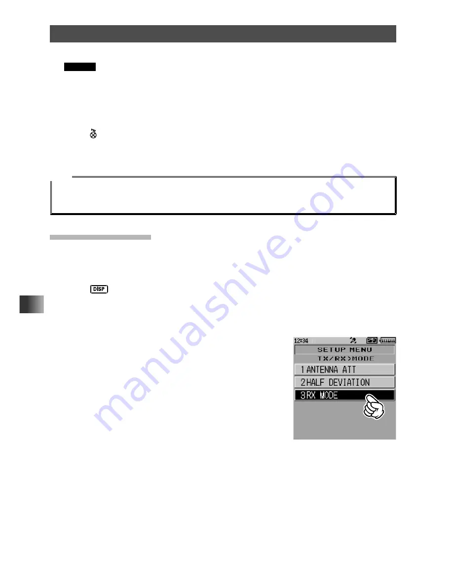
Changing the Mode

The operating mode of the selected band may be changed.
By  default,  “AUTO  (Auto  Mode)”  is  set  so  that  the  typical  operating  mode  (radio  wave 
type) is automatically selected according to the frequency band in use.

1

  Press 

 key for over one second.


The transceiver enters Set mode.

2

  Touch 

[TX/RX]

.

3

  Touch 

[1 MODE]

.

4

  Touch 

[3 RX MODE]

.


The current setting will be displayed.

Summary of Contents for FT2DR

Page 1: ...sic Operation Repeater Operation Using the Memory Scanning Function Digital Group Monitor Function Using the APRS Functions Using the WIRES X Functions Using the GPS Function Convenient Functions Comm...

Page 2: ...e 39 Transmitting Receiving Signals 40 Listening to the Radio 42 Listening to the AM FM Radio 42 Miscellaneous Settings 43 Setting Clock Time 43 Muting Audio 44 Changing the Transmission Power Level 4...

Page 3: ...93 Real Time Navigation Function 93 Backtrack Function 93 Registering Your Current Position Departure Point up to 3 Positions can Be Registered 93 Using the Back Track Function 94 Description of the...

Page 4: ...l Protect Function 137 Setting Memory Skip Function 137 Setting the Memory Channels Used for Registration 137 Set Mode SIGNALING Menu Operations 138 Notification of a Call from a Remote Station by the...

Page 5: ...52 Set Mode APRS Menu Operations 153 Set Mode SD CARD Menu Operations 154 Saving Loading Data to from microSD Memory Card 154 Saving Loading Memory Channel Information to from microSD Memory Card 155...

Page 6: ...memory channels 65 By selecting preset frequencies you can receive shortwave broadcast and international VHF radio stations with ease A wide variety of scan functions 71 Built in GPS unit allowing di...

Page 7: ...e to the characteristics of the LCD when the ambient temperature is low the touch screen may respond slowly Touch Screen Upkeep After turning off the transceiver wipe the touch screen with a soft dry...

Page 8: ...and U suffix is for use with 230 VAC Type BF plug Antenna Belt clip Battery pack protective cap Long life lithium ion battery pack SBR 14LI 7 2V 2 200 mAh USB cable Quick Manual Operating Manual this...

Page 9: ...ibited action not to be done in order to use this product safely For example indicates that the product should not be disassembled Indicates a required action to be done in order to use this product s...

Page 10: ...when the included antenna and battery pack are installed and rubber caps are securely attached to the MIC SP jack EXTDC IN jack DATA terminal and micro SD slot If this transceiver gets wet wipe it wit...

Page 11: ...case with thinner or benzene Use a soft dry cloth to clean the case If the transceiver is not being used for an extended period turn it off and remove the battery pack for safety Do not drop strike or...

Page 12: ...nplugging the power cord of the battery charger be sure to hold the power plug Pulling the power cord can damage it and cause a fire or electronic shock Before discarding the worn battery pack affix t...

Page 13: ...int Cleaning When this product is contaminated with seawater sand or dirt rinse with fresh water and then wipe with a dry cloth immediately Recommended maintenance interval To insure continued water r...

Page 14: ...o return to the previous screen x key In normal mode press to start WIRES X When WIRES X is activated press and hold for over one second to return to the normal mode Battery pack DIAL Rotate to change...

Page 15: ...nal and micro SD slot are securely covered with rubber caps the FT2DR DE meets the waterproofing performance conforming to IPX5 See page 13 Touch Screen Display This is the A band display area This is...

Page 16: ...ssion T D Lights when the transceiver is set to send the CTCSS tone signal during transmit and wait for the DCS code in receive mode D T Lights when the transceiver is set to send the DCS code during...

Page 17: ...ssion side Touching MODE each time switches the operation mode Function Menu Screen Touching F MW displays the function menu screen Band Scope Screen The band scope screen can be displayed by touching...

Page 18: ...e received station on the compass icon only when the received signal carries the position information Touching MY displays your station s heading direction on the compass icon Touching MEM switches to...

Page 19: ...ter input screen Touch the 1 key to display the numeric 2 byte character keypad input screen Touch the 123 key to display the numeric keypad input screen Touch to display the symbol input screen Touch...

Page 20: ...nnecting to an external antenna ensure that the SWR is adjusted to 1 5 or lower Attaching the Accessory Protective Cap Belt Clip Attaching the Protective Cap If you do not use the belt clip install th...

Page 21: ...ceiver and thread the strap through the loop to secure it to the transceiver The hand strap is not supplied 1 Remove the battery pack 2 Attach the hand strap Caution Use a hand strap which can withsta...

Page 22: ...your fingers and nails Charging the Battery Pack Cautions The battery pack is rechargeable about 300 times However improper use such as overcharge or over discharge can shorten its service life The b...

Page 23: ...s in battery pack Rapid Charger Cradle CD 41 optional Rails 1 Install the battery pack 2 Turn the transceiver off 3 Insert the plug of the battery charger PA 48 or SAD 14B into the EXT DC IN jack of t...

Page 24: ...electrode gets dirty clean it using a dry cloth or cotton swab Tips The battery charger may become hot during charging This is not a malfunction If starts blinking the battery pack charge is depleted...

Page 25: ...e the alkaline batteries in the battery case Caution of the alkaline batteries 3 Close the cover Push the four corners of the cover firmly to close it tightly Tip When the battery charge is low batter...

Page 26: ...shorten its service life Be extremely careful not to continually recharge the battery when operating the transceiver using an external power supply While charging the battery pack protect the transcei...

Page 27: ...er supply remove the supplied antenna and connect an external antenna Place the external power supply Do not continue transmitting for a prolonged period The transceiver may overheat resulting in malf...

Page 28: ...the Battery Pack External Power Supply Tips turned on while the battery pack is charging the charging time will increase slightly If the transceiver is connected to the external power supply with the...

Page 29: ...or place heavy objects on the microSD memory card microSD memory cards formatted on other devices may not properly save information transceiver when using memory cards formatted with another device Do...

Page 30: ...the microSD memory card 4 Close the microSD cover 5 Press and hold for over one second The transceiver will turn on When the microSD memory card is properly detected lights on the display Tip Removing...

Page 31: ...ry Card Formatting a microSD Memory Card Caution microSD memory card you are using be sure to check the data saved on it before formatting 1 Press and hold key for over one second 2 Touch SD CARD 3 To...

Page 32: ...Select a Frequency Band Turn in to a Frequency Perform Communication Turning on the Transceiver 1 Press and hold for over one second When the transceiver is turned on for the first time after purchase...

Page 33: ...and are displayed simultaneously Supplement Factory settings are A band upper 144 000 MHz B band lower 430 000 MHz Tip You can change the information such as the power supply voltage and the opening m...

Page 34: ...ng to white noise Toggling the Operating Band Normally both operating bands are displayed on the top half and bottom half of the transceiver touch screen This is Dual band With one of the bands select...

Page 35: ...e Name Date and Voltage display Touching the Name Date and Voltage display switches the screen to the tag display A band operating band B band A band B band operating band Press Press and hold for ove...

Page 36: ...Hz 174 MHz 144 MHz band 174 MHz 222 MHz 222 MHz 420 MHz INFO band 1 420 MHz 774 800 MHz 430 MHz band 470 MHz 770 MHz 803 800 MHz 999MHz INFO band 2 Cellular Blocked USA Version 108 MHz 137 MHz AIR ban...

Page 37: ...he key to switch the frequency bands in reverse order Available frequency bands differ depending on the band The following frequency bands can be used for A band and B band Frequency bands on A band S...

Page 38: ...36 To recall the home channel of each frequency band touch F MW followed by HOME see page 57 Tuning to a Frequency Tune to the desired frequency using either of the following methods Rotate the DIAL t...

Page 39: ...uency band To change the tuning so the frequency will move repeatedly through the selected band press and hold for over one second to switch to Set mode then touch CONFIG 21 VFO MODE and select BAND t...

Page 40: ...o the received signal Always switches to VW mode for transmission AUTO Automatically selects one of the 4 communication modes according to the received signal V D Mode Voice Data simultaneous transmis...

Page 41: ...may be burned Wait for the temperature inside the transceiver to cool sufficiently before resuming transmission Do not start transmitting without attaching the antenna The transmitter circuit can be...

Page 42: ...y to set the A band as the operating band 2 Press the key to select either the AM broadcast or FM broadcast band 3 Rotate the DIAL or display the numeric keypad input screen to tune in to the desired...

Page 43: ...transceiver enters Set mode 2 Touch CONFIG 3 Rotate the DIAL then touch 19 DATE TIME ADJ Cursors appear and blink at the last 2 digits of the year 4 Rotate the DIAL to select the year then press the k...

Page 44: ...matically The lithium battery can power the clock for approximately 2 months When you use the transceiver for the first time or without the battery pack for a long period of time the accuracy of the c...

Page 45: ...E 30 MUTE 50 MUTE 100 The higher the value for MUTE the more the non operating band audio is reduced To deactivate the muting function select OFF 6 Press The transceiver exits from Set mode Remark Whe...

Page 46: ...IGH High Power LOW3 LOW2 LOW1 USA EXP European Battery pack 5W 2 5W 1W 0 1W 0 05W VHF 0 1W UHF External power supply DC13 8V Battery Case alkaline battery Approx 0 8W 0 05W VHF 0 1W UHF 1 Touch F MW 2...

Page 47: ...ed operating band 2 Press 3 Rotate the DIAL to adjust the squelch level Remarks The squelch level can be adjusted within the range from 0 to 15 Default LEVEL 1 FM radio broadcast band is LEVEL 2 4 Pre...

Page 48: ...Hz to 136 991 MHz the frequency step 8 33 kHz can also be selected For bands covering 250 MHz to 300 MHz and bands covering 580 MHz or higher the frequency steps 5 kHz 6 25 kHz and 15 kHz cannot be se...

Page 49: ...m radio band 144 MHz band or 430 MHz band transmission will continue to be in the FM mode Caution The mode of the A band AM FM broadcast radio bands cannot be changed Locking Keys and Switches To prev...

Page 50: ...ing you from hearing the remote station signal switch the attenuator to ON When there is no reception problem there is no need to switch the attenuator ON 1 Press and hold the key for over one second...

Page 51: ...cel resetting touch CANCEL 5 Press the key The call sign input screen appears 6 Input your call sign Switch the display between the alphabet keys and number keys to input the call sign 7 Press The cal...

Page 52: ...tically be set to the programmed offset frequency and CTCSS tone Tips Touching F MW followed by REV enters the reverse state where the transmission frequency and the receive frequency are temporarily...

Page 53: ...RS 1 Press and hold the key for over one second The transceiver enters Set mode 2 Touch CONFIG 3 Rotate the DIAL then touch 14 RPT ARS 4 Rotate the DIAL to select ON to enable Automatic Repeater Shift...

Page 54: ...72 50 sets of memory channels L1 U1 to L50 U50 for programmable memory channel scanning PMS see page 81 The operating frequency and other operational information can be registered to each regular memo...

Page 55: ...allows programming 900 memory channels memory channel numbers 1 to 900 1 Press the key to enter VFO mode 2 Rotate the DIAL to tune to the frequency to be registered to a memory channel 3 Touch F MW f...

Page 56: ...memory channel automatically appears To display the lowest unregistered memory number when registering a frequency to a memory channel press and hold key for over one second to enter Set mode and then...

Page 57: ...e displayed Tips Unregistered memory channels are skipped By default memory channel number 1 is used as a dual receive priority memory channel P appears on the upper right corner of the priority memor...

Page 58: ...430 000 MHz 50 MHz 50 000 MHz 470 to 770 MHz band 47 000 MHz AIR band 108 000 MHz Information radio band 2 860 000 MHz 144 MHz band 146 520 144 000 MHz Returning to the Previous Frequency 1 Touch F MW...

Page 59: ...specified priority memory channel To clear a priority memory channel cancel the priority setting of the memory channel Restoring the Cleared Memories The cleared memory channels may be restored 1 Pre...

Page 60: ...annel to assign the name Tip To assign a name to a home channel recall the desired home channel 3 Press and hold for over one second The transceiver enters Set mode 4 Touch MEMORY 5 Touch 3 MEMORY NAM...

Page 61: ...ey to enter Memory mode 2 Press and hold the key for over one second The mono band operation display appears and the name tag appears under the frequency The name tag also appears under the frequency...

Page 62: ...ata on a memory channel is edited or updated the data on the corresponding memory channel in the memory banks is automatically edited or updated Registering to Memory Banks 1 Press the key to enter Me...

Page 63: ...key to enter Memory mode 2 Touch F MW 3 Touch BANK 4 Press the key 5 Rotate the DIAL to select the desired memory bank 6 Press the key The memory bank to be used is determined 7 Rotate the DIAL to se...

Page 64: ...racters Numbers Symbols 1 Press and hold the key for over one second The transceiver enters Set mode 2 Touch MEMORY 3 Rotate the DIAL then touch 2 BANK NAME 4 Rotate the DIAL to select a memory bank S...

Page 65: ...uencies 10 channel used for the VHF Weather Broadcast Station are regis tered to the dedicated preset receiver memory channels International VHF Marine Radio preset receiver memory channels INTVHF are...

Page 66: ...equency appears on the LCD Recalling Preset Receiver Memory Channel to Listen to the Weather Broadcast The frequencies 10 channels used for the VHF Weather Broadcast Station are registered in the dedi...

Page 67: ...her frequency or data To scan the preset receiver memory channels toward higher channel numbers touch F MW followed by SCAN To scan the preset receiver memory channels toward lower channel numbers rot...

Page 68: ...0 650 MHz and lights up The frequency lower than the base station frequency by 4 6 MHz is the Ship Station frequency and duplex operation may commence To return to the base station frequency press F M...

Page 69: ...h Republic 38 6 105 CZECH Czech Republic 39 9 455 CZECH Czech Republic 40 11 860 CZECH Czech Republic 41 9 780 PORTUGAL Portugal 42 11 630 PORTUGAL Portugal CH Number Frequency MHz Name Broadcast Stat...

Page 70: ...s CH Number Frequency MHz Name Broadcast Station Name 85 11 860 JAPAN Japan 86 5 995 AUSTRALIA Australia 87 9 580 AUSTRALIA Australia CH Number Frequency MHz Name Broadcast Station Name 88 9 660 AUSTR...

Page 71: ...VFO Scan Memory Channel Scan Programmable Memory Channel Scan PMS VFO Scan 1 Press the key to switch the transceiver to VFO mode 2 Press the key to select the operating band you want to scan 3 Touch...

Page 72: ...g To exit scanning touch STOP or press Tips To set the transceiver action when scanning stops see Setting the Receive Operation When Scanning Stops on page 74 Press and hold the key for over one secon...

Page 73: ...elow to register the frequencies you do not want to scan to the skip search memory channels in advance 1 In VFO mode tune in to the frequency you do not want to scan 2 Touch F MW for over one second 3...

Page 74: ...ed frequency by repeating steps 1 through 4 then touching M REX Setting the Receive Operation When Scanning Stops When scanning stops one of the following three receiving options may be chosen 1 The s...

Page 75: ...EC TO 10 SEC 0 5SEC STEP BUSY and HOLD 6 Press The reception method is set and the transceiver exits from Set mode Tips The reception method selected here is applied to VFO Scanning Programmable Memor...

Page 76: ...emains illuminated After receiving the signal for 5 seconds scanning resumes Press to cancel scanning Tips When a memory channel is recalled the regular memory channels memory channel numbers 1 900 ar...

Page 77: ...channel scanning Alternatively you can specify that only designated memory channels are scanned during memory scanning 1 Press the key to enter Memory mode 2 Rotate the DIAL to show the memory channe...

Page 78: ...memory channel registered as a specified memory channel 3 Touch F MW The function menu appears on the LCD 4 Touch SCAN Tips Rotate the DIAL clockwise to start scanning toward higher frequencies Only...

Page 79: ...imal point blinks and the LCD stays lit After receiving the frequency for 5 seconds scanning resumes To stop scanning press You can select the range for scanning by pressing and holding the key for ov...

Page 80: ...wer memory channel numbers When a signal is received during scanning scanning stops for 5 seconds and this frequency is received When scanning is suspended the decimal point blinks and the LCD stays l...

Page 81: ...y band Programmable memory channel scanning does not function if the frequency bands are different Performing Programmable Memory Channel Scan The programmable memory channel scan allows setting a spe...

Page 82: ...program memory channel scanning does not function Press and hold the key for over one second to enter Set mode then configure the following operating preference settings CONFIG 3 BEEP EDGE Sets wheth...

Page 83: ...e GM function does not operate in analog mode Before activating GM function Touch MODE to switch to the AMS Auto Mode Select Function or digital mode Standard Operation of the GM Function There are tw...

Page 84: ...up name Example of display when GROUP is set For details on how to setup a group and register members to it refer to the GM Function Instruction Manual which is available on the Yaesu website Deactiva...

Page 85: ...of the remote station and other data sent by the remote station may be displayed on the LCD of your transceiver Example of display when an APRS signal is received Setting several station parameters s...

Page 86: ...longitude and altitude within a tolerance of several meters In addition GPS can receive the exact time from the satellite onboard atomic clock Activating the GPS Function Activating the GPS function e...

Page 87: ...egistered position information can be set as the position of your station When the GPS function is active the power consumption increases by about 30 mA As a result the battery life is reduced by abou...

Page 88: ...t 3 satellites need to be acquired for successful positioning If positioning fails move away from buildings as far as possible and stand in an area with open sky The measurement environment may result...

Page 89: ...e second The transceiver enters Set mode 3 Touch CONFIG 4 Touch 6 GPS LOG 5 Rotate the DIAL to select the GPS data logging interval The selectable setting values are as follows When OFF is set the pos...

Page 90: ...lable memory card reader 4 Open the FT2D folder in the microSD memory card 5 Open the GPSLOG folder The data is saved as GPSyymmddhhmmss log The yymmddhhmmss part of the name consists of year yy month...

Page 91: ...th N or south S latitude Display format X DD MM MMM X X N North latitude X S South latitude DD Degree MM MMM Minute Example N 35 38 250 35 degrees 38 minutes 15 seconds north latitude The current posi...

Page 92: ...m of WGS 84 it is recommended not to change it The time zone may be set at 30 minute increments by pressing and holding the key for over 1 second to enter Set mode then selecting APRS 28 TIME ZONE the...

Page 93: ...n and direction of the remote station can be displayed in real time even during communication 1 Press the key The navigation screen appears 2 Touch YR The distance and direction to the remote station...

Page 94: ...ister the position information The location information is registered with the selected indicator and the screen returns to the back track screen 5 Press the key The screen returns to the normal frequ...

Page 95: ...e arrow so that the arrow stays pointing up on the screen 3 Press the key The screen returns to the normal frequency display To confirm the position again press the key to display the back track scree...

Page 96: ...ion on the selected memory channel While receiving a signal on the frequency registered to a priority memory channel pressing disables the Dual Receive function and allows transmission over the same f...

Page 97: ...el number blinks 3 Rotate the DIAL to select the desired memory channel 4 Touch The memory channel to preferentially receive Priority Memory Channel is selected The P appears on the LCD 5 Press the ke...

Page 98: ...LCD 5 Select the memory channel you want to constantly receive 6 Touch F MW 7 Touch DW The HOME Channel Dual Reception starts and MDW appears on the LCD 8 Touch The Memory Channel Dual Receive is canc...

Page 99: ...t to the Memory Channel number 1 by default Press and hold the key for over one second to enter Set mode then configure the following settings for more convenient use SCAN The time interval for monito...

Page 100: ...signal on the specified memory channel during radio reception the radio reception is interrupted approximately every 5 seconds When using the AF DUAL Receive Function the radio reception is interrupte...

Page 101: ...y bank Pressing during radio reception allows receiving the standby frequency While listening to the radio using the AF DUAL function in standby receive mode the transceiver cannot simultaneously rece...

Page 102: ...nds to resume broadcast reception in 5 seconds after ham band reception or transmission ends Fixed While receiving a radio broadcast using the AF DUAL Receive function the ham radio band A band or B b...

Page 103: ...Up to 10 registers of 16 digit DTMF tone codes can be stored as telephone numbers to make calls through the public telephone network using a phone patch 1 Press and hold the key for over one second Th...

Page 104: ...Rotate the DIAL to select then press the key 5 Rotate the DIAL to select 6 Press The auto dialer is enabled 7 Press Displays DTMF 8 While pressing and holding touch DTMF Displays the numeric keypad s...

Page 105: ...ars on the LCD 8 While pressing touch DTMF The numeric keypad appears 9 Use the numeric keypad to input the DTMF code Tips The registered DTMF code is transmitted Refer to the following table The tran...

Page 106: ...To resume band scope scanning touch 5 Press the key Tips Press and hold the key for over one second to enter Set mode then select 3 The number of band scope channels can be changed to 17 or 71 The ban...

Page 107: ...graph Do not touch the lens with fingers or other objects Microphone Speak into this part with a normal voice Clip Securely clip the microphone to belt or other objects Connect to the DATA terminal of...

Page 108: ...rop the MH 85A11U Applying a strong shock may result in damages or failure The captured image appears on the LCD 5 To save the image onto the microSD memory card touch Press the key or touch returns t...

Page 109: ...uiet while waiting for a call from a specific station over a long period of time Cautions The tone squelch function does not function in digital mode Touch MODE to switch the communication mode to AMS...

Page 110: ...ommunications based on the squelch control system in which a tone signal is contained when communication is not performed and the tone signal disappears when communication starts PR FREQ Activates the...

Page 111: ...n 1 Press and hold the key for over one second The transceiver enters Set mode 2 Touch SIGNALING 3 Rotate the DIAL then touch 11 SQL TYPE 4 Rotate the DIAL to select TONE SQL 5 Press the key 6 Rotate...

Page 112: ...e 2 Touch SIGNALING 3 Touch 2 DCS CODE 4 Rotate the DIAL to select the desired DCS code 5 Gently press the key 3 times The DCS code is set and the transceiver exits from Set mode Tip The default setti...

Page 113: ...setting how the transceiver operates when scanning stops see Setting the Receive Operation When Scanning Stops on page 74 Notification of a Call from a Remote Station by Vibration Set the vibrator to...

Page 114: ...The transceiver enters Set mode 2 Touch CONFIG 3 Touch 22 VIBRATOR then press the key 4 Rotate the DIAL to select SELECT then press the key 5 Rotate the DIAL to select the desired vibrator operation...

Page 115: ...function is on appears on the LCD When a signal is received from a remote station blinks When a signal is received from a remote station blinks When pressing to perform transmission stops blinking an...

Page 116: ...s received Caution The new pager function does not function in digital mode Touch MODE to switch the communication mode to AMS Automatic Mode Select Function or analog mode in advance Flow of Operatio...

Page 117: ...personal code are reversed i e 47 05 from 05 47 they are still recognized as the same code If the same code is specified for all individuals all the individuals can be called at the same time Activat...

Page 118: ...ss The code is set and the transceiver exits from Set mode 9 Press The remote station is called Being Called by the Remote Station Standby Operation If you turn on the Bell Function see page 114 you a...

Page 119: ...cting various functions from the list and setting each function according individual preferences Set Mode Operation 1 Press and hold the key for over one second The transceiver enters Set mode 2 Touch...

Page 120: ...ansceiver 2 While pressing the and keys simultaneously press for over one second The transceiver turns ON When you hear a beep sound release the keys 3 After SET MODE RESET appears touch OK A beep sou...

Page 121: ...0 S METER SYMBOL Select the symbol used for the S PO meter 4 types 131 11 SOFTWARE VERSION Display the software version Main Sub DSP 131 TX RX 1 MODE 1 1 ANTENNA ATT Switch the attenuator between ON O...

Page 122: ...Set the transmission of DTMF code registered to a DTMF memory channel DTMF code transmission delay time and DTMF code transmission speed MODE MANUAL AUTO DELAY 50ms 250ms 450ms 750ms 1000ms SPEED 50ms...

Page 123: ...NUAL PRESET 2 SEARCH SETUP Set the WIRES ROOM selection method HISTORY ACTIVITY 3 EDIT CATEGORY TAG Edit category tags C1 to C5 4 REMOVE ROOM NODE Delete registered Category ROOMs C1 to C5 For details...

Page 124: ...TIME ADJ Set the built in clock 43 20 TOT Set the timeout timer OFF 30 SEC to 10 MIN European version 3 MIN 152 21 VFO MODE Select the frequency selection range in the VFO mode ALL BAND 152 22 VIBRATO...

Page 125: ...ER MY PACKET MSG GRP and BLN are as follows OFF ALL2s to ALL60s ALLCNT BND2s to BND60s BNDCNT ALL10s The setting values of MY MSG DUP BCN DUP MSG ACK REJ and OTHER MSG are as follows OFF BND2s to BND6...

Page 126: ...MEA9 NMEA6 NMEA7 NMEA8 Mic E ON OFF POSIT ON OFF WEATHER ON OFF OBJECT ON OFF ITEM ON OFF 18 DIGI PATH Set the digital repeater route P1 OFF P2 1 1 WIDE1 1 P3 2 1 WIDE2 1 2 WIDE2 1 P4 2 1 2 P5 2 1 2 P...

Page 127: ...s of the functions refer to the APRS Instruction Manual SD CARD 1 BACKUP Save the data stored on the transceiver onto a microSD memory card or load the data from a microSD card Write to SD Read from S...

Page 128: ...compass NUMERIC Displays the latitude and longitude Remark The default setting COMPASS Setting the Compass Display Set the compass display 1 Touch 2 COMPASS 2 Rotate the DIAL to select the desired set...

Page 129: ...tus after the set illumination time elapses OFF After the illumination time selected for KEY elapses the lights dim to LEVEL 1 of the LCD dimmer setting ON After the illumination time selected for KEY...

Page 130: ...the receive frequency instead of the opening message immediately after turning on the power DC Displays the power supply voltage and time when turning on the power MESSAGE Displays a message comprisin...

Page 131: ...e desired display pattern of the S Meter 1 Rotate the DIAL then touch 10 S METER SYMBOL 2 Rotate the DIAL to select the desired display pattern 1 2 3 4 Remark The default setting 1 Displaying the Soft...

Page 132: ...rferes with reception use the attenuator ATT function to reduce interference by selecting 1 MODE 1 ANTENNA ATT For details see Attenuator ATT Function except AM broadcasts and AM broadcasts on page 50...

Page 133: ...nding SQL CODE BREAK Audio is output regardless of any squelch code when the remote station transmits with BREAK set Remark The default setting OFF 5 Press the key 6 Rotate the DIAL to select SQL CODE...

Page 134: ...tes transmission 1 Touch 2 DIGITAL 2 Touch 4 STANDBY BEEP 3 Rotate the DIAL to select the desired setting ON Emits the standby beep sound OFF Does not emit the standby beep sound Remark The default se...

Page 135: ...on operating band can be muted by selecting 3 AUDIO 2 MUTE For details see Muting Audio on page 44 Simultaneous Radio Broadcast Reception Set the time to resume radio broadcast reception after transmi...

Page 136: ...Touch 1 BANK LINK 2 Rotate the DIAL to select the memory bank you want to link then press the key The checkbox is checked 3 Repeat step 2 to link the memory banks one by one from BANK 1 to BANK 24 As...

Page 137: ...Memory Skip Function By selecting 5 MEMORY SKIP you can set the scan method for scanning memory channels For details see Specifying Skip Selected Memory Channels on page 77 Setting the Memory Channel...

Page 138: ...DCS code out of the 104 codes from 023 to 754 by selecting 2 DCS CODE For more details see Setting the DCS Code on page 112 Transmitting and Receiving a DCS Code with an Inverted Phase DCS INVERSION F...

Page 139: ...6 PAGER For details see Calling Only a Specific Station New Pager Function on page 116 Enabling No communication Squelch Function PR FREQUENCY Function Set a no communication squelch frequency in ste...

Page 140: ...S Meter level 2 LEVEL3 Outputs the audio of a signal as strong or stronger than the S Meter level 3 LEVEL4 Outputs the audio of a signal as strong or stronger than the S Meter level 4 LEVEL5 Outputs...

Page 141: ...o be changed 1 Rotate the DIAL then touch 13 TONE SRCH 2 Rotate the DIAL to select MUTE then press the key 3 Rotate the DIAL to select the desired setting ON Mutes the audio during the tone search ope...

Page 142: ...SEC Remark The default setting 5 0 seconds Setting the Illumination On Off When Scanning Stops LAMP Function Set whether or not the LCD backlight is turned on when a signal is received during scanning...

Page 143: ...the current frequency scans within the current band 4 Press the key 5 Rotate the DIAL to select MEMORY then press the key 6 Rotate the DIAL to select the desired setting referring to the table below A...

Page 144: ...mode For details on how to set each item refer to FT2DR DE GM Function Instruction Manual which is available on Yaesu website Set Mode WIRES X Menu Operations Press and hold the key for over one secon...

Page 145: ...s off the power when no operation is performed for a specified period of time Remark The default setting OFF Tips When the auto power off function is active appears on the LCD Once the time for automa...

Page 146: ...KEY SCAN 4 Press the 5 Rotate the DIAL to select EDGE then press the key 6 Rotate the DIAL to select the desired setting referring to the table below OFF No confirmation sound is emitted when a band...

Page 147: ...SD memory card 1 Touch 6 GPS LOG 2 Rotate the DIAL to select the time interval OFF 1 SEC 2 SEC 5 SEC 10 SEC 30 SEC 60 SEC If OFF is selected no GPS Information is saved onto the microSD memory card Re...

Page 148: ...IAL and keys on the front side of the transceiver PTT Locks KEY PTT Locks and the keys on the front side of the transceiver DIAL PTT Locks the DIAL and ALL Locks the DIAL and the keys on the front sid...

Page 149: ...o deactivate the timer function Remark The default setting TIMER OFF Password Function You can enter a 4 digit password to prevent a third party from using your transceiver without permission Once a p...

Page 150: ...after is pressed 1 Rotate the DIAL then touch 13 PTT DELAY 2 Rotate the DIAL to select the desired setting OFF 20ms 50ms 100ms 200ms Selecting OFF disables the PTT delay time function Remark The defau...

Page 151: ...erval sleep ratio to reduce power consumption 1 Rotate the DIAL then touch 17 SAVE RX 2 Rotate the DIAL to select the desired setting the time interval for disabling the receiver operation 0 2 sec 1 1...

Page 152: ...seconds later the transceiver returns to the receive mode The TOT setting is retained until OFF is selected in step 2 above Setting the Frequency Selection Range for Operation in VFO Mode VFO MODE Fun...

Page 153: ...tions Press and hold the key for over one second to display SETUP MENU then touch APRS to set the individual items After completing the setup press to exit from Set mode For details on setting each it...

Page 154: ...transceiver 1 Rotate the DIAL then touch 1 BACKUP 2 Rotate the DIAL to select the operation to be performed Write to SD Saves the transceiver setting information to a microSD memory card Read from SD...

Page 155: ...selected and data reading completes a beep sounds then the transceiver restarts with the settings read from the microSD memory card applied Saving Loading GROUP ID Information to from a microSD Memor...

Page 156: ...ing completes a beep sounds and COMPLETED appears on the LCD When Read from SD is selected and data reading completes a beep sounds then the transceiver restarts with the settings read from the microS...

Page 157: ...ng image size settings 160 120 320 240 Remark The default setting 160 120 4 Press the key 5 Rotate the DIAL to select QUALITY then press the key 6 Rotate the DIAL to select one of the following image...

Page 158: ...LSIGN Menu Operations Press and hold the key for over one second to display SETUP MENU then touch CALLSIGN for the call sign setting 1 See Entering Letters on page 19 to input the call sign then press...

Page 159: ...is continued for a long time the overheat prevention circuit will operate and the transmission power decreases If the transmission is continued further the transmission will be automatically stopped t...

Page 160: ...arts the display on the receiving transceiver changes from WAIT to RX On the transmission side transceiver when data transmission begins the transmission data amount indicator appears on the LCD On th...

Page 161: ...ur current location information on the map software etc Tips For details on setting 17 COM PORT SETTING see Set mode in the APRS Instruction Manual To display the location information software compati...

Page 162: ...commercially available GPS receivers or other external devices by using the optional Data Cable CT 170 Tip Connect the Data Cable CT 170 and the Data Output Cable CT 176 referring to the instruction...

Page 163: ...ery Charger SAD 14B for USA market Speaker Microphone with Snapshot camera MH 85A11U Clone Cable CT 168 Data Cable CT 170 PC connection cable SCU 19 PC connection cable CT 169 Belt Clip SHB 13 B suffi...

Page 164: ...l of squelch or S meter squelch when receiving a weak signal Is the volume low Rotate the VOL knob clockwise to increase the volume Is the tone squelch or DCS on When the tone squelch or DCS is on the...

Page 165: ...tery packs are consumables Please replace the battery pack with a new one immediately Battery packs can be charged and reused up to approximately 300 times Depending on the combination for simultaneou...

Page 166: ...onvenient Functions 96 D Deleting the Frequency Registered to the Skip Search Memory Channel 73 Digital Group Monitor Function 83 Displaying the Battery Voltage 130 Displaying the Memory Tag 61 Displa...

Page 167: ...etting the DCS Code 112 Setting the DTMF Code 139 Setting the Key Operation Confirmation Sound 146 Setting the Memory Channels Used for Registration 137 Setting the Operation of the Key 148 Setting th...

Page 168: ...15 20 25 50 100 kHz Mode of Emission F1D F2D F3E F7W Frequency Stability Operating Temperature Range Supply Voltage Nominal 7 2 V DC Negative Ground SBR 14LI Nominal 7 4 V DC Negative Ground FNB 101LI...

Page 169: ...1 V TYP for 12 dB SINAD 54 76 88 MHz NFM 1 5 V TYP for 12 dB SINAD 76 88 108 MHz WFM 1 5 V TYP for 10 dB SN 108 137 MHz AM 0 2 V for 12 dB SINAD 137 140 MHz NFM 0 16 V for 12 dB SINAD 140 150 MHz NFM...

Page 170: ...ate this device 2 The scanning receiver in this equipment is incapable of tuning or readily being altered by the User to operate within the frequency bands allocated to the Domestic public Cellular Te...

Page 171: ...ddress 6125 Phyllis Drive Cypress CA 90630 U S A Telephone 714 827 7600 Disposal of your Electronic and Electric Equipment Products with the symbol crossed out wheeled bin cannot be disposed as househ...

Page 172: ...172 Appendix Declaration of Conformity Applicable Standards Yaesu UK Ltd Unit 12 Sun Valley Business Park Winnall Close Winchester SO23 OLB United Kingdom Email sales yaesu co uk...

Page 173: ...U USA 6125 Phyllis Drive Cypress CA 90630 U S A YAESU UK Unit 12 Sun Valley Business Park Winnall Close Winchester Hampshire SO23 0LB U K Copyright 2015 YAESU MUSEN CO LTD All rights reserved No porti...

Reviews: