background image

28

14. 

Under the Pose List column, select the pose to edit.

You can edit a pose by one of two ways, manually adjust the smart servos or through the use of 
the slide bars under each appendage designation. The following instructions provide a step-by-
step instructions of both procedures.

Warning:

  The user is about to move the Bolide so we need to tell them. Be careful and do not put 

your hands near the Bolide when it is moving. Use the same warning we have in the 
beginning.

a. 

In the bottom toolbar, click 

Relax

 to release the smart servos and allow you to move 

them freely.

b. 

Select a smart servo and adjust it to a desired position. This is the position that will be 
associated with the selected pose.

c. 

Click 

Capture

 to save the settings to the selected Pose.

d. 

Click 

Set

 after adjusting slide bars.

OR

a. 

Select a pose from the Pose List.

b. 

Click 

Live Pose Update

 to adjust the actual position of a selected smart servo.

c. 

Select a smart servo, and adjust the slide bar to a desired smart servo position.

d. 

Click 

Set

 after adjusting slide bars.

Creating a Sequence

Follow the procedure to create a sequence:

1. 

Connect the Bolide Y-01 to your computer. Connect one end of a USB cable to the computer 
(USB Type A) and the other end to the Bolide Y-01 (USB Type Mini-B).

2. 

Once connected, power up the Bolide Y-01, see “Testing the Bolide Y-01” in the assembly 
manual.

3. 

Locate and open the XYZrobot Editor application.

4. 

From the toolbar select 

Tool > Sequence List

.

5. 

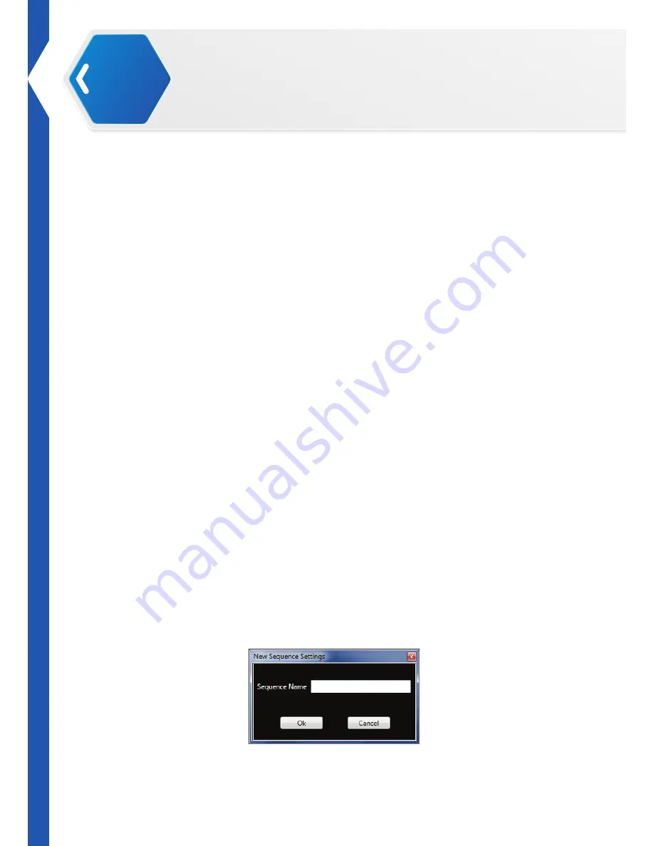
Click 

Add

 to create a new sequence entry. The New Sequence window displays.

6. 

In the open field, enter the name of the sequence entry and click 

Ok

 to continue.

Operations

02

Summary of Contents for Bolide Y-01

Page 1: ...Bolide Y 01 Construct of Your Imagination ...

Page 2: ...lug the robot Ensure the robot does not tip over or fall down Remove the battery remove 1 screw on the back of the battery casing To prevent the spread of fire keep candles or other open flames away from the robot at all times At all times keep in mind safety first to prevent injury to individuals using or around the robot Always follow installation and service instructions closely Keep manuals fo...

Page 3: ...nment The equipment must not be co located or operating in conjunction with any other antenna or transmitter Battery Safety Warning DO NOT throw the battery in fire DO NOT short circuit the contacts DO NOT disassemble the battery DO NOT throw the battery in municipal waste The symbol of the crossed out wheeled bin indicates that the battery should not be placed in municipal waste Important Notice ...

Page 4: ... operation seems erratic Procedure for handling in a potentially hazardous event 1 Pick up the robot by bar even if it is still moving 2 Press the Power On Off button to turn off 3 Put the robot in the starting default posture Refer to the User Guide for powering on instructions In case of a power emergency do not touch the robot CAUTION Pinching Hazard Avoid carrying and touching the robot when i...

Page 5: ... maximum battery lifespan fully charge the battery at least once every 3 months Protect the AC adapter terminals from dirt or other foreign objects CAUTION To avoid electric shock Do not plug the power cables into an electrical outlet if the power cable is damaged During a storm unplug the AC adapter from the socket to protect it from damage Never use an AC adapter that shows signs of damage or ex...

Page 6: ...r If using an extension cable make sure that the total ampere rating of the products plugged in to the extension power cable does not exceed the ampere rating of the extension cable Use an extension cable or power board designed for grounded plugs and plugged into a grounded wall outlet Working Area Start from the default posture before turning on the robot When turned off it is best to keep the r...

Page 7: ...ables from a power socket or extension cable and only attempt this if it is safe to do so Liquids spilt onto the robot or AC adapter may cause a short circuit and stop the robot from working The warranty is automatically void if any liquid seeps inside the AC adapter whether apparent from the outside or not Do not use the robot in a wet environment Do not connect or disconnect the battery or AC ad...

Page 8: ...bot 2 Turn off the robot 3 Place the robot in the default posture 4 Dry the robot as much as possible 5 Disconnect and remove the battery casing 6 Let the robot air dry completely before installing the battery casing 7 Once completely dry install the battery casing 8 Turn on the robot NOTE For information on your warranty coverage see the Warranty in this assembly manual ...

Page 9: ...s 12 Overview of Installation Process 12 Read Me First 13 Existing Arduino Installations 13 First Time Installation 14 Setting Up Hardware and Libraries 15 Installing the Bolide Y 01 Editor Driver 16 Installing the Editor Software 18 Overview 18 Installing the XYZrobot Editor 18 Uninstalling the XYZrobot Editor 20 Updating the Software 20 Operations 21 Introduction 21 Interface Menus 21 Main Menu ...

Page 10: ...cal Components 37 Additional Components 37 Adapters 37 MicroSD Card 37 Hardware Installation 38 Installing the MicroSD Card 38 Control Panel 39 Remote Control Default Motion 40 Maintenance 41 LED Codes 41 Definition List 41 USB Drivers 42 Installing a USB FTDI Driver 42 Installing Bolide Y 01 Default Firmware 43 Validating Environment Setup 44 Smart servos 45 Querying Servo Status 45 Setting a Ser...

Page 11: ...ites Windows Operating System Requirements Windows 7 or later Including both 32 bit and 64 bit versions Microsoft Net Framework 4 5 Mac Operating System Requirements Mac OS X 10 8 or later Arduino Arduino IDE 1 0 6 ...

Page 12: ...ime The software will also allow you to create action sequences by combining the created pose list in any number of combinations For more information about the XYZrobot Editor visit XYZprinting Inc at http www xyzrobot com Bolide Software Pack The software pack includes the following items ArduinoSetting Setup the Arduino environment for Bolide Y 01 A1_16_ID_Setting Set A1 16 smart servo ID Bolide...

Page 13: ...yzrobot com 3 If you haven t already download the Arduino application At this time the Bolide Y 01 only supports version 1 0 6 See the following information to download the applicable software package Windows http arduino cc download php f arduino 1 0 6 windows exe Mac OS X http arduino cc download php f arduino 1 0 6 macosx zip Overview of Installation Process Review all instructions and informat...

Page 14: ...ibrary folder and the included contents allowing you to extend use of previosly saved files For users that have a previously installed Arduinio package in their computer system see Unsupported Versions on page 13 For users that do not currently have the Arduino application installed see First Time Installation on page 14 section Existing Arduino Installations Unsupported Versions The Bolide Y 01 r...

Page 15: ...min priviledges to being the installation process If you do not have admin privileges see your network administrator or use the Non Admin Installation version 1 Download the Arduino software only version 1 0 6 is supported Windows http arduino cc download php f arduino 1 0 6 windows exe Mac OS X http arduino cc download php f arduino 1 0 6 macosx zip 2 Click the installer file to start the install...

Page 16: ... 4 Navigate to the local drive which contains the installed Arduino software Locate the hardware folder For example My Documents Arduino hardware If a hardware folder is not available in the Arduino directory add a new folder and rename it hardware For Mac users the folder structure will be different 5 Paste the XYZrobot file as listed in the previous steps in the hardware folder The Arduino hardw...

Page 17: ...equenced movement steps The motion editor makes use of the Arduino open source software requiring the installation of Arduino on your system if not done so at this point and synchronizing it to your Bolide Y 01 The following instructions guide you through the complete installation of the driver required for the Motion Editor 1 Connect the Bolide Y 01 to your computer Connect one end of a USB cable...

Page 18: ...and select the associated option NOTE If the device is not detected the USB driver may not be recognized The option to select the associated COM port will not be available You will need to update or re install the serial port drivers see USB Drivers on page 42 7 Click Verify to compile the codes After compiling the message Done compiling displays on the bottom of the frame If there are no errors a...

Page 19: ...wing section for step by step instructions on installing the XYZrobot Editor software Installing the XYZrobot Editor Before installing the XYZrobot Editor download the driver from http www xyzrobot com 1 Locate the downloaded driver file 2 Click setup exe to run the application The Launching Application window displays Follow the on screen prompts to continue NOTE At the time of writing the file a...

Page 20: ...us Once the installation is complete the XYZrobot Motion Editor software opens NOTE A security prompt may display requiring authorization to open the software To continue with the procedure click OK to continue or cancel to end the process 01 Software ...

Page 21: ...rs 1 Drag the app from the Applications folder to the Trash located at the end of the Dock 2 Then choose Finder Empty Trash The XYZrobot Editor application is removed from the program list WARNING Emptying the Trash bin permanently removes the content and are no longer available NOTE The screens and procedure may vary slightly depending on the operating system in use Updating the Software During t...

Page 22: ...itial display viewed when the XYZrobot Editor is opened The following table provides a description of the menu names and a brief description of their function 7 6 5 2 1 3 4 No Item Description 1 Project Open to create new open existing save save as projects See Project on page 22 2 Tool Open to select the type of function screen to display Pose or Sequence editor or select the Export to AVR format...

Page 23: ...ue movement and sequence definitions See Main Menu on page 21 Project Item Description New Create a new project Open Open a saved project file Save Save the current file Save As Save the current file as a new project file Tool Item Description Pose Editor Switch main menu to pose editor Sequence Editor Switch main menu to sequence editor Export to AVR Export the current settings to a h file Config...

Page 24: ...ou to directly adjust the smart servo position Do not place your hands around the Bolide Y 01 and make sure there is sufficient space around the Bolide Y 01 for unobstructed movement to avoid personal injury or damage to the unit 6 Set Send the current desired position settings to the Bolide Y 01 board The signal is then sent to each smart servo to match the desired position 7 Capture Capture the ...

Page 25: ...0 degrees while a reading of 1023 defines a 330 turn NOTE The function is only accessible when a project is connected and a Pose is selected 10 Slide bar Move the slide bar to manually adjust the actual position of the smart servo NOTE A reading of 0 sets the desired position to 0 degrees while a reading of 1023 defines a 330 turn The smart servo can not rotate outside of these parameters Operatio...

Page 26: ...ct a pose from the drop down menu 8 Delay ms Click the selector arrows to adjust the time variable Type a specific number and press Enter to manually set a delay variable milliseconds 9 Move up Move the order of the selected pose up in the order 10 Add Add a post for the sequence 11 Halt Initiate a stop command when a sequence is running 12 Loop Initiate a continuous run command for the selected s...

Page 27: ...e Bolide Y 01 and computer through a USB cable The following procedure provides detailed instructions to allow you to create a pose 1 Connect the Bolide Y 01 to your computer Connect one end of a USB cable to the computer USB Type A and the other end to the Bolide Y 01 USB Type Mini B 2 Once connected power up the Bolide Y 01 see Testing the Bolide Y 01 in the assembly manual 3 Locate and open the...

Page 28: ...0 Click Ok to continue 11 Select Tool Pose Editor 12 Under Pose List click Add to create a new pose 13 The New Pose Settings window displays In the Pose Name field enter a name for the pose and click Ok to create the new entry The entry is created with all default positions To customize the new pose you will need to modify the position of the limbs on the Bolide and capture the settings In this wa...

Page 29: ...apture to save the settings to the selected Pose d Click Set after adjusting slide bars OR a Select a pose from the Pose List b Click Live Pose Update to adjust the actual position of a selected smart servo c Select a smart servo and adjust the slide bar to a desired smart servo position d Click Set after adjusting slide bars Creating a Sequence Follow the procedure to create a sequence 1 Connect ...

Page 30: ...der in which the pose list is executed 10 To re order a pose under Pose List select a pose entry and click Move Up or Move Down to position the entry into your desired order 11 Once the sequence is designed you can initiate a test to view the pose selections performed by the Bolide Y 01 12 Select the a sequence from the Sequence List 13 Click Run to run the selected sequence Alternatively you can ...

Page 31: ... the advanced configuration procedures See Basic Editing on page 26 To create an AVR file 1 Select Projector Open and select an xyz file to open 2 Select Tool Export to AVR to save an h file for use with the Arduino application 3 Close the XYZrobot Editor 4 Open the previously saved AVR file h format NOTE Open the AVR file using a general text editor such as Notepad as h files cannot be opened in ...

Page 32: ...dy for the configuration process see Programming the Control Panel on page 32 or Programming the Remote Control on page 33 12 Under the section User Sequence Setup select an entry In the following example the entry selection is define New 115 13 Under the column UserSequenceName enter a name to personalize the entry In the following example the selection is renamed s1 The name set here must match ...

Page 33: ...t Button define RB_1 115 default 34 define RB_2 33 default 33 define RB_3 32 default 32 define RB_4 35 default 35 9 From the menu toolbar click Tools Board and select the option XYZrobot BOLIDE option NOTE If the previously mentioned Tool Board option is not available the Arduino Library structure has not been setup To setup the Arduino Library for the hardware see Setting Up Hardware and Librarie...

Page 34: ...emote control buttons To match the new sequence to the selected button on the remote control 1 Before starting this procedure see Before You Start on page 30 2 Connect the Bolide Y 01 to your computer Connect one end of a USB cable to the computer USB Type A and the other end to the Bolide Y 01 USB Type Mini B 3 Once connected power up the Bolide Y 01 see Testing the Bolide Y 01 in the assembly ma...

Page 35: ...eviously mentioned Tool Board option is not available the Arduino Library structure has not been setup To setup the Arduino Library for the hardware see Setting Up Hardware and Libraries on page 15 9 Next select the COM port associated with the Bolide Y 01 From the menu toolbar click Tool Serial Port and select the associated option NOTE If the device is not detected the USB driver may not be reco...

Page 36: ...ton Mapping L3 R3 RELEASE L1 L2 R1 R2 1 2 3 14 13 12 4 6 5 7 10 8 11 9 02 Operations 1 RCU_R3 2 RCU_R2 3 RCU_R1 4 RCU_RJU 5 RCU_RJR 6 RCU_RJD 7 RCU_RJL 8 RCU_LJD 9 RCU_LJL 10 RCU_LJU 11 RCU_LJR 12 RCU_L1 13 RCU_L2 14 RCU_L3 ...

Page 37: ... Bolide Y 01 with greater ease Apps are available for iOS and Android based operating systems To download your respective app in Google Play or the APP Store use the keyword XYZrobot to locate and download the latest Bolide Y 01 application To get further information on the user interface control functions and programming download the Bolide Y 01 APP user manual found on the XYZprinting Inc websit...

Page 38: ... on regional requirements MicroSD Card The microSD slot is designed for microSD cards for the purpose of playing music when a function button is pressed Only WAV formatted files are supported The file name needs to match the format 0000 9999 03 Mechanical Components ...

Page 39: ...lot on the Bolide Y 01 2 Hold the microSD card with the arrow pointing towards the slot and carefully slide into the slot until it clicks in place CAUTION Do not force a microSD card into the slot Orient the microSD card prior to insertion Forcing a microSD card into the slot may cause damage to the slot and the microSD card Mechanical Components 03 ...

Page 40: ...ttons found just above the battery see following illustration The function buttons are pre programmed for a specific action They can also be manually programmed for presonalized preferences 1 Power switch 2 Function button 1 3 Function button 2 4 Function button 3 5 Function button 4 03 Mechanical Components ...

Page 41: ...w 7 Turn left 8 Transmit LED 9 Bluetooth LED 10 Receive LED 11 Bluetooth connect 12 Power 13 Emergency release 14 Walk forward 15 Right 16 Walk backward 17 Left 18 Salute 19 Push up 20 KungFu fighting L3 R3 RELEASE L1 L2 R1 R2 13 1 20 12 11 9 8 10 3 18 2 19 4 6 5 7 14 16 15 17 Mechanical Components 03 ...

Page 42: ...Bluetooth LED Receive LED Description LED on Red LED on Red LED on Red Power on LED on Green LED off LED on Green Unconnected LED on Green LED on Red LED on Green Pairing LED on Red LED on Blue LED on Green Connected Data transmitted LED on Green LED on Blue LED on Red Connected Data received LED on Orange LED on Blue LED on Orange Press power button Smart Servo LED Status Error Error LED on off N...

Page 43: ...able at this time disconnect the USB cable 11 Turn on the Bolide Y 01 if it isn t powered on already Then re connect the USB cable from the Bolide Y 01 to a USB port on your system The operating system detects the new USB connection In the Device Manager a new Flagged item appears under Other Devices 12 Right click on the detected device and right click on it to open up the Properties menu 13 From...

Page 44: ..._Y 01_Default ino to run the application 5 From the menu toolbar click Tools Board and select the option XYZrobot BOLIDE option NOTE If the previously mentioned Tool Board option is not available the Arduino Library structure has not been setup To setup the Arduino Library for the hardware see Setting Up Hardware and Libraries on page 15 6 Next select the COM port associated with the Bolide Y 01 F...

Page 45: ...ploading displays on the bottom of the frame The Bolide Y 01 returns to default position and an audible alert sounds indicating a successful upload Validating Environment Setup Once the software is installed and the driver code is uploaded to the Bolide Y 01 validating a successful upload is easily obtained The resulting code upload will Return the Bolide Y 01 to the default position An audible al...

Page 46: ...nd click Send All the smart servo status shows in the window Setting a Smart Servo ID 1 Disconnect all cables from the MCU board 2 Connect the new smart servo and MCU board via the supported cable 3 Locate the Bolide software pack and navigate to the following folder Bolide_Y 01_Arduino_Support_File_20151201 A1_16_ID_Setting For the latest software visit the http www xyzrobot com 4 Click A1_16_ID_...

Page 47: ...river If you have problems with other products or can t solve the problem with the instructions above please contact your regional manager Display Done uploading but still shows error message when burn program 1 The electricity is low Please fully charge the Li ion battery or connect the adaptor and try again 2 The selected COM port is wrong Select Config Port Setting Select the current connected ...

Page 48: ......

Reviews: