background image

18

19

5.  Wait for the temperature reading to stabilize, then press enter 

to complete the calibration or press Cal 

 to cancel. 

6.  ‘Calibration Successful’ will display for a few seconds to indicate 

a successful calibration and then the instrument will return to 
the Run screen.

7.  If the calibration is unsuccessful, an error message will display 

on the screen. Press the Cal key to exit the calibration error 
message and return to the Run screen.  See the Troubleshooting 
section of this manual for possible solutions.   

condUctIvIty calIBratIon

Ensure the conductivity sensor is clean and dry before performing a 
conductivity, specific conductance or salinity calibration. 

It is not necessary to calibrate conductivity, specific conductance 
and salinity. Calibrating one of these parameters will simultaneously 
calibrate the others. YSI recommends calibrating specific conductance 
for greatest ease.

Always calibrate with fresh, traceable calibration solution with a value 
of 1000 uS or more.  

Note: 1 mS = 1000 uS

CALIBRATING SPECIFIC CoNDUCTANCE 
(SPC) oR CoNDUCTIVITY

Note:  When calibrating Specific Conductance, the Pro1030 uses 
the factory default values for the Specific Conductance Reference 
Temperature and the Specific Conductance Temperature Coefficient 
regardless of what is configured in the System Setup Menu. The default 
value for the Reference Temperature is 25°C and the default value for 
the Temperature Coefficient is 1.91%/°C. It is important to note that 
the Temperature Coefficient of a calibration solution is dependent 
on the contents of the solution. Therefore, for highest accuracy, YSI 
recommends using a traceable calibration solution made of KCl 
(potassium chloride) when calibrating Specific Conductance since 
these solutions typically have a Temperature Coefficient of 1.91%/°C. 
Additionally, be sure to enter the value of the solution as it is listed for 
25°C when calibrating Specific Conductance.  

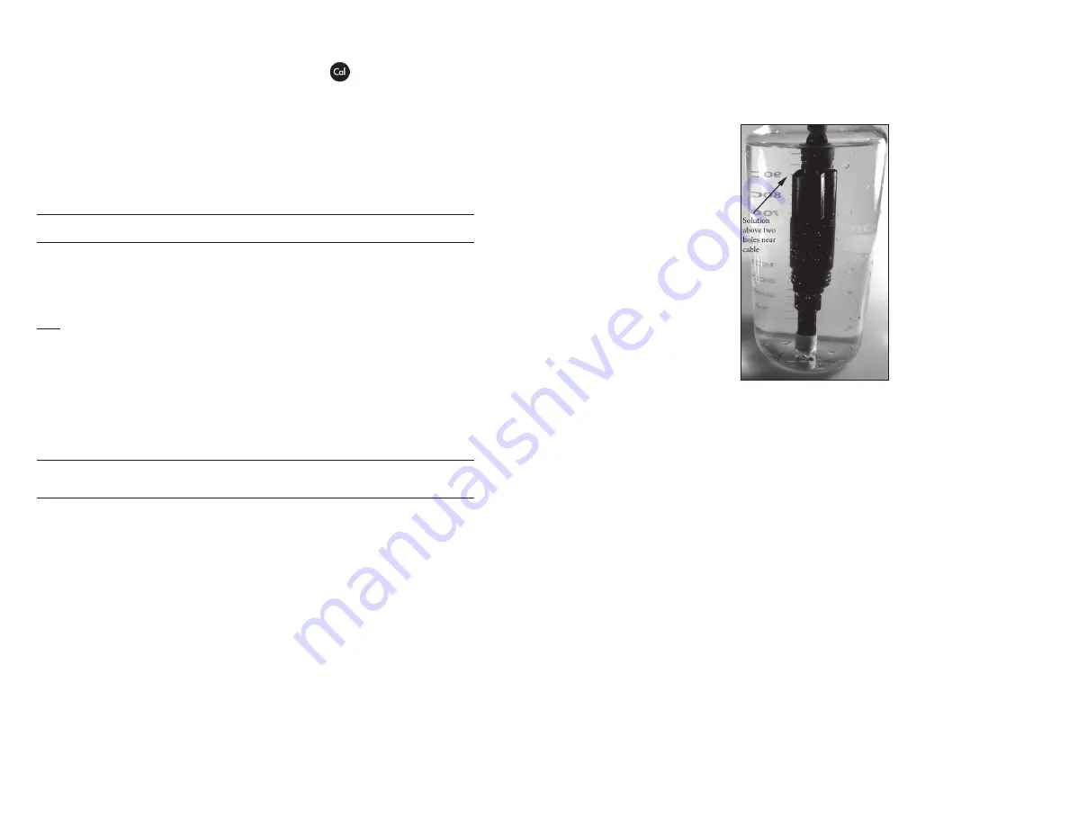
1.  Place the sensor into the solution. The solution must cover the 

holes of the conductivity sensor that are closest to the cable 

(figure 8). Ensure the entire conductivity sensor is submerged in 
the solution or the instrument will read approximately half the 
expected value. Gently move the probe up and down to remove 
any air bubbles from the conductivity sensor.

Figure 8, solution above two holes near cable.  

2.  Turn the instrument on and allow the conductivity and 

temperature readings to stabilize. Press and hold the Cal key 
for 3 seconds. Highlight Conductivity and press enter. Next, 
highlight the desired calibration method, Sp. Conductance or 
Conductivity, and press enter. 

3.  Highlight the units you wish to calibrate, either uS/cm or mS/cm, 

and press enter. 1 mS = 1,000 uS. 

4.  Use the up or down arrow key to adjust the value on the display 

to match the value of the conductivity calibration solution. 
Most conductivity solutions are labeled with a value at 25°C. If 
calibrating specific conductance, enter the value listed for 25°C. 
If calibrating conductivity, look up the value of the solution at 
the solution’s current temperature and enter that value into the 
Pro1030. Press and holding either the up or down arrow key for 
5 seconds will move the changing digit one place to the left. 
The Pro1030 will remember the entered calibration value and 
display it the next time a conductivity calibration is performed.

5.  Press enter to complete the calibration or press Cal to cancel.    
6.  ‘Calibration Successful’ will display for a few seconds to indicate 

a successful calibration and then the instrument will return to 
the Run screen.

Summary of Contents for YSI Pro1030

Page 1: ...USER MANUAL English Pro1030...

Page 2: ...First Power On 7 System Setup Menu 7 Audio 8 Contrast 8 Temperature Units 8 ISE Sensor Type 9 ISE Units 9 Auto Stable 9 pH Buffer Set 10 Conductivity Units Cond Units 10 Specific Conductance Reference...

Page 3: ...red by this warranty To exercise this warranty call your local YSI representative or contact YSI Customer Service in Yellow Springs Ohio at 1 937 767 7241 800 897 4151 or visit www YSI com for a Produ...

Page 4: ...pack the instrument and accessories and inspect for damage Compare received parts with items on the packing list If any parts or materials are damaged or missing contact YSI Customer Service at 800 89...

Page 5: ...u from the Run screen 2 Up Arrow Use to navigate through menus to navigate through box options along the bottom of the Run screen and to increase numerical inputs 3 Power and Backlight Press once to t...

Page 6: ...y 1 o ring visible Failure to properly seat the sensor may result in damage 6 Twist the sensor clockwise to engage the threads and finger tighten Do NOT use a tool This connection is water tight The I...

Page 7: ...System Setup menu the up and down arrow keys will move the highlighted bar up and down the system setup options See the System Setup menu section of this manual for more information about these option...

Page 8: ...ther pH model 1001 or ORP model 1002 Use the up or down arrow keys to highlight ISE Sensor Type then press enter to open a submenu Highlight the sensor type corresponding to the sensor installed on th...

Page 9: ...enter to enable or disable it An enabled conductivity unit will have an X in the box next to it Highlight the ESC Exit box along the bottom of the display and press enter to save any changes and to cl...

Page 10: ...e a multiplier for the water at your sampling site Use the following procedure to determine the multiplier for a specific sample 1 Determine the specific conductance of a water sample from the site 2...

Page 11: ...e and 10 seconds pH Buffer Set USA Conductivity Units cond mS cm and spc mS cm Parameter Reset Defaults Conductivity Auto Stable Off 0 0 Change and 10 seconds SPC Reference Temperature 25 C SPC Temper...

Page 12: ...hold Cal for three seconds 3 Highlight pH and press enter If pH is not listed as an option check the System Setup menu to ensure pH is enabled in the ISE Sensor Type menu 4 Highlight 3 point and pres...

Page 13: ...hloride when calibrating Specific Conductance since these solutions typically have a Temperature Coefficient of 1 91 C Additionally be sure to enter the value of the solution as it is listed for 25 C...

Page 14: ...ess the Cal key to exit the calibration error message and return to the Run screen See the Troubleshooting section of this manual for possible solutions Taking M easurements Before taking measurements...

Page 15: ...the data set number 01 through 50 Erasing Data While viewing saved data press the enter key to access the function boxes at the bottom of the display Next use the up or down arrow keys to highlight E...

Page 16: ...prevent water from entering the port Once the ISE sensor is removed examine the connector inside the port If any moisture is present use compressed air to completely dry the connector or let it air d...

Page 17: ...h all parts of the sensor tip without stress You can also use a pipe cleaner for this operation if more convenient i Dry the port and sensor connector with compressed air and apply a very thin coat of...

Page 18: ...displays Calibration Over Calibration Under or Unstable Reading during calibration 1 Ensure the conductivity sensor is clean Follow the cleaning procedures in the Care Maintenance and Storage section...

Page 19: ...uctivity 0 500 uS cm 0 5 mS cm 0 50 mS cm 0 200 mS cm auto ranging 0 0001 to 0 1 mS cm 0 1 to 0 uS cm range dependent Instrument only 0 5 of the reading or 1 uS cm whichever is greater Instrument with...

Reviews: