background image

6

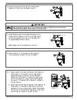
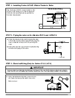
STEP 3 - Installing Series 47 Water Feeder or Series 47-2 Combination Water 

Feeder/Low Water Cut-Off with Quick Hook-Up Fittings to Boiler

a.

Apply thread sealant to the external threads 
of the "Y" fittings (T). Using the pipe wrench, 
install them in the boiler gauge glass tappings (S),
and tighten to approximately 54 ft

lb (74 N

m).

Tighten both union nuts (U).

b.

Reinstall water glass and gauge connections to “Y”
fittings (T).

When using pipe or tape sealant on the external threads of pipes or fittings, follow the manufacturers 
instructions. Use sparingly and do not place on the first thread.

!

IMPORTANT

U

N

L

U

U

T

S

R

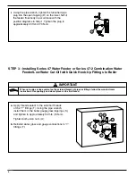
i.

Using the pipe wrench, tighten the furnished pipe 
plug into the open tapping (R) on the lower half of 
the feeder float body in accordance with the 
position diagrams in Step 1. Tighten the plug to 
approximately 20 ft

lb (27

.

3 N

m).

Summary of Contents for McDonnell & Miller 247 Series

Page 1: ...nt Low Water Cut Off controls be installed on all steam boilers with heat input greater than 400 000 BTU hour or operating above 15 psi steam pressure At least two controls should be connected in seri...

Page 2: ...2 NPT 47 47 2 Maximum Boiler Pressure 25 psi 1 76 kg cm2 247 247 2 Maximum Boiler Pressure 30 psi 2 1 kg cm2 Electrical Ratings Series 47 Water Feeders and Series 47 2 Combination Water Feeder Low Wat...

Page 3: ...GS PARALLEL TO BOILER WITH TURNEDY FITTINGS 3 STEP 1 Determine Best Position to Install the Water Feeder to clear obstructions that may be encountered on the side of the boiler INSTALLATION TOOLS NEED...

Page 4: ...E are greater than 14 356 mm apart invert the black Y casting F as depicted in the diagram to the bottom right and install a longer nipple G F INVERTED Y CASTING Note Reverse union nuts packing and p...

Page 5: ...onnection Slide union nut U over tailpiece P Using a pipe wrench tighten the tailpiece P into the 1 2 15 mm NPT tapping Q in the lower half of body K Tighten to 54 ft lb 74 N m 5 J H K e Remove the pl...

Page 6: ...b 74 N m Tighten both union nuts U b Reinstall water glass and gauge connections to Y fittings T When using pipe or tape sealant on the external threads of pipes or fittings follow the manufacturers i...

Page 7: ...lectrical Wiring Only for Series 47 2 247 2 AA a Using the flathead screwdriver loosen the two 2 screws that secure the switch cover AA Remove cover 7 IMPORTANT Boiler manufacturer schematics should a...

Page 8: ...in the diagram to the right Low water cut off switch and or low water alarm Pilot switch for motor starter or relay The feeder should be blown down after initial installation before leaving site It s...

Page 9: ...he flooding Broken Union Test E D B H x 4 A Using a 1 2 socket wrench unscrew the four 4 hex head bolts B that secure the strainer basket H to the valve assembly E B Using a 13 16 socket wrench unscre...

Page 10: ...er Solution Replace float e Cause Equalizing piping is plugged Solution Clean or replace piping f Cause Water supply is above 150 psi Solution Install pressure reducing valve to reduce water pressure...

Page 11: ...surfaces DO NOT use sharp objects to scrape off any accumulations of sediment or debris Unit is making noise a Cause Under certain system conditions there may be a vibration when the valve mechanism...

Page 12: ...er needs Developing new technologies that will improve the way water is used conserved and re used in the future is central to our work We move treat analyze and return water to the environment and we...

Reviews: