


F
G
g.
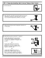
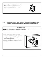
Slide the black "Y" (F) casting over the nipple (G)
in accordance with Step 2d, but do not tighten.
L
F
M
N
L
P
U
U
K
Q
Q
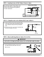
h.
1). Apply sealant to the external threads of the nipple (L)
of the upper "Y" connection. Using a pipe wrench,
tighten the nipple (L) into the 1/2" (15 mm) NPT
tapping (M) of the black "Y" casting (F). Slide union
nut (U) over nipple (L). Using a pipe wrench tighten
the upper “Y” connection (N) to nipple (L). Tighten to
54 ft
•
lb (74 N
•
m).
2). Apply sealant to the external threads of the tailpiece (P)
of the lower "Y" connection. Slide union nut (U) over
tailpiece (P). Using a pipe wrench, tighten the tailpiece
(P) into the 1/2” (15 mm) NPT tapping (Q) in the lower
half of body (K). Tighten to 54 ft
•
lb (74 N
•
m).
5
J
H
K
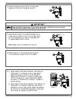
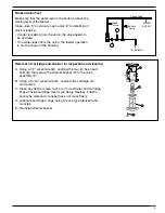
e.
Remove the plug (H) from the 1/2" (15 mm) NPT
tapping (J) in the top of the feeder body (K).
J
G
K
No Threads
f.
Apply thread sealant to the external threads. Using
a pipe wrench, tighten the 1/2" (15 mm) NPT nipple
(G) into the tapping (J) on the top of the feeder (K)
to approximately 54 ft
•
lb (74 N
•
m).
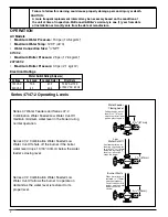
Note:
Nipple (G) is only threaded on one end.
Upper “Y”
Lower “Y”
When using pipe or tape sealant on the external threads of pipes or fittings, follow the manufacturers
instructions. Use sparingly and do not place on the first thread.
!
IMPORTANT


