


Series 8100/8150/8200/9100 Fire Pump
19
AC6102 Rev 0
5
7.5.2.1 Angular Alignment
To check angular alignment, mount dial indicator (A) to the
coupling half (X), and position the dial indicators button on the
face of the opposite coupling half (Y). Scribe index lines on
both coupling hubs as shown in Fig. 10. Set the dial to zero,
rotate both coupling halves together, so that the index lines
match; ensuring that the indicator button always indicates off
the same spot. Check the coupling manufacturer’s guidelines
for the acceptable alignment tolerances.
7.5.2.2 Parallel Alignment
To check parallel alignment, mount dial indicator (P) to the
coupling half (X), and position the dial indicators button on the
outside diameter of the opposite coupling half (Y), (see Fig.
10). Set the dial to zero, rotate both coupling halves together,
so that the index lines match; ensuring that the indicator
button always indicates off the same spot. Check the coupling
manufacturer’s guidelines for the acceptable alignment
tolerances.
7.5.3
Alignment of grid couplings
The following procedure is intended for mounting and
alignment of Rexnord Industries, LLC and Clarke Fire
Protection Products, Inc., Type T10 Close Coupled Grid
Couplings.
Alignment is shown using a spacer bar and straight edge,
which has been prove to be accurate for many industrial
applications. However, for superior final alignment, the use of
dial indicators is recommended, per 7.5.2.
7.5.3.1 Mount Seal and Hubs
Clean all metal parts using non-flammable solvent. Coat the
seals lightly with coupling manufacturer supplied grease and
place on shafts before mounting shaft hubs. Install keys and
mount hubs with flange faces flush with the shaft ends.
Reposition hubs on shafts as required achieving the hub gap
specified in table 5. The length of engagement on each shaft
should be approximately equal to the shaft diameter. Tighten
the setscrews.
7.5.3.2 Gap and Angular Alignment (X-Y)
Use a spacer bar equal to thickness to the gap specified in
Table 5. Insert bar, as shown above to the same depth at 90°
intervals and measure clearance between the bar and hub
face with feeler gage. The difference in minimum and
maximum measurements must not exceed the angular
installation limits specified in Table 5.
Fig. 11
Using Spacer Bar
7.5.3.3 Parallel Offset Alignment (P)
Align so that a straight edge rests squarely, (or within the
limits specified in Table 5 on both hubs as shown above and
also at 90° intervals, (see Fig. 12). Check with feeler gages.
The clearance must not exceed the Parallel Offset installation
limits specified in Table 5.
If adjustment is needed, loosen the motor bolts and add or
remove an equal amount of shims under each motor foot to
align the height. To correct side misalignment, strike the side
of the motor foot with a mallet.
Tighten the motor bolts and check again. Re-check alignment
in all directions, if a correction is made. Repeat the process
until the desired result is obtained.
Fig. 12
Using Straight edge
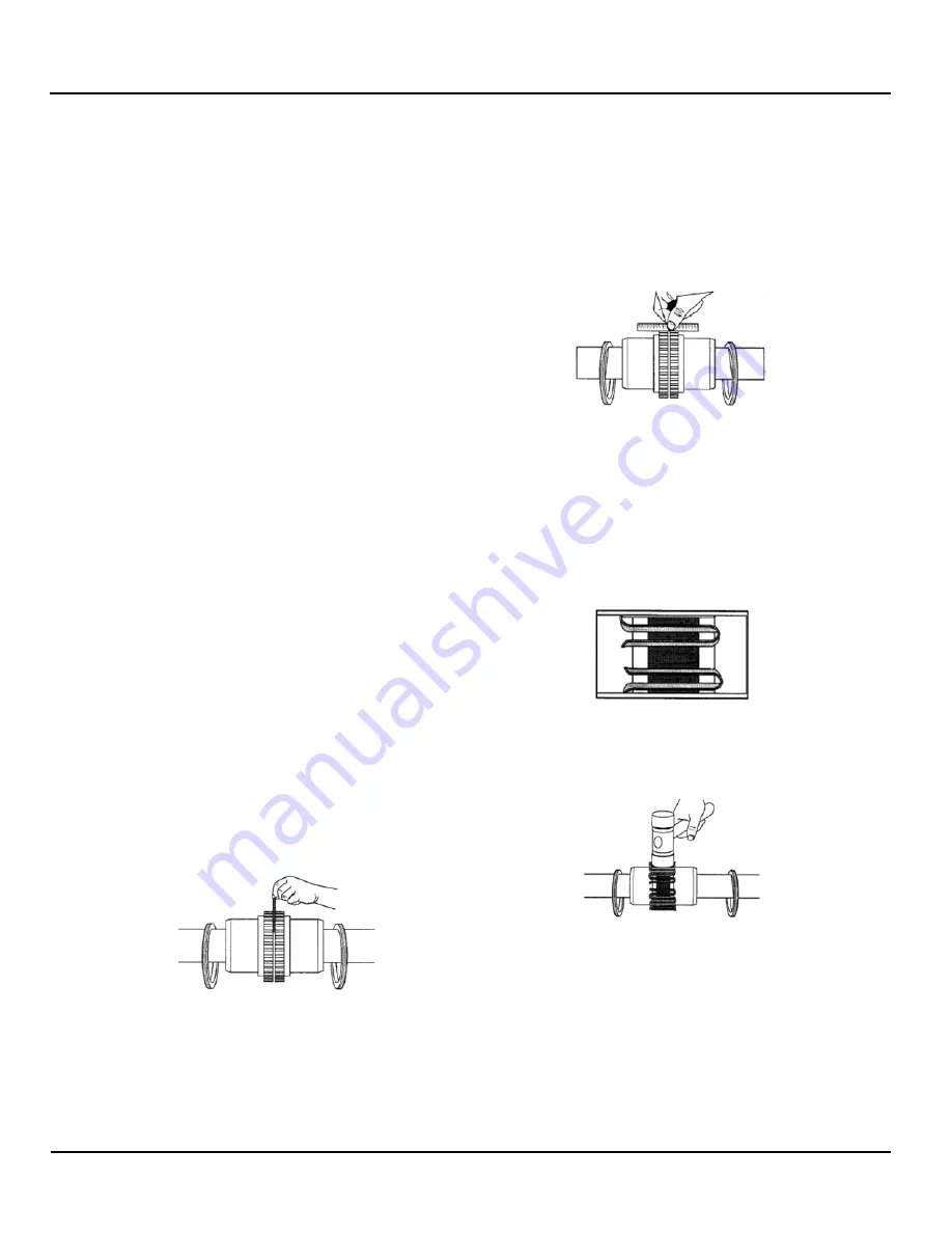
7.5.3.4 Insert Grid
Completely pack gap and grooves with coupling manufacturer
supplied grease before inserting grid. When grids are
furnished in two or more segments, install them so that all cut
ends extend in the same direction as shown in Fig. 13. This
will ensure correct grid contact with non-rotating pin in cover
halves.
Fig. 13
Grids magnified
Spread the grid slightly to pass over the coupling teeth and
seat with a soft mallet, (see Fig. 14).
Fig. 14
Seating the grid
7.5.3.5 Pack with grease and assemble covers
Completely pack the spaces between and around the grid
with as much grease as possible and wipe off excess flush
with top of the grid. Position seals on hubs to line up with the
grooves in the cover. Position gaskets on flange of lower
cover half and assemble covers so that the match marks are
on the same side, (see Fig. 15). Secure cover halves with
fasteners tightening to torque specified in Table 5.
Summary of Contents for AC Fire Pump 8100 Series
Page 2: ...Series 8100 8150 8200 9100 Fire Pump 1 AC6102 Rev 05...
Page 4: ...Series 8100 8150 8200 9100 Fire Pump 3 AC6102 Rev 05...
Page 8: ...Series 8100 8150 8200 9100 Fire Pump 7 AC6102 Rev 05...
Page 41: ...AC6102 Rev 05 40 Table 14 Troubleshooting List...
Page 50: ...Series 8100 8150 8200 9100 Fire Pump 49 AC6102 Rev 05 A Appendix...


