background image


Wall-Mount Installtion 


Installations with Multi-Use Brackets 

4-Bracket 19” Rackmount Installtion 


9


Note: Fix a M5*10 screw on eight places marked with letter B. 


Appearance dimension of M5*10 screw. 


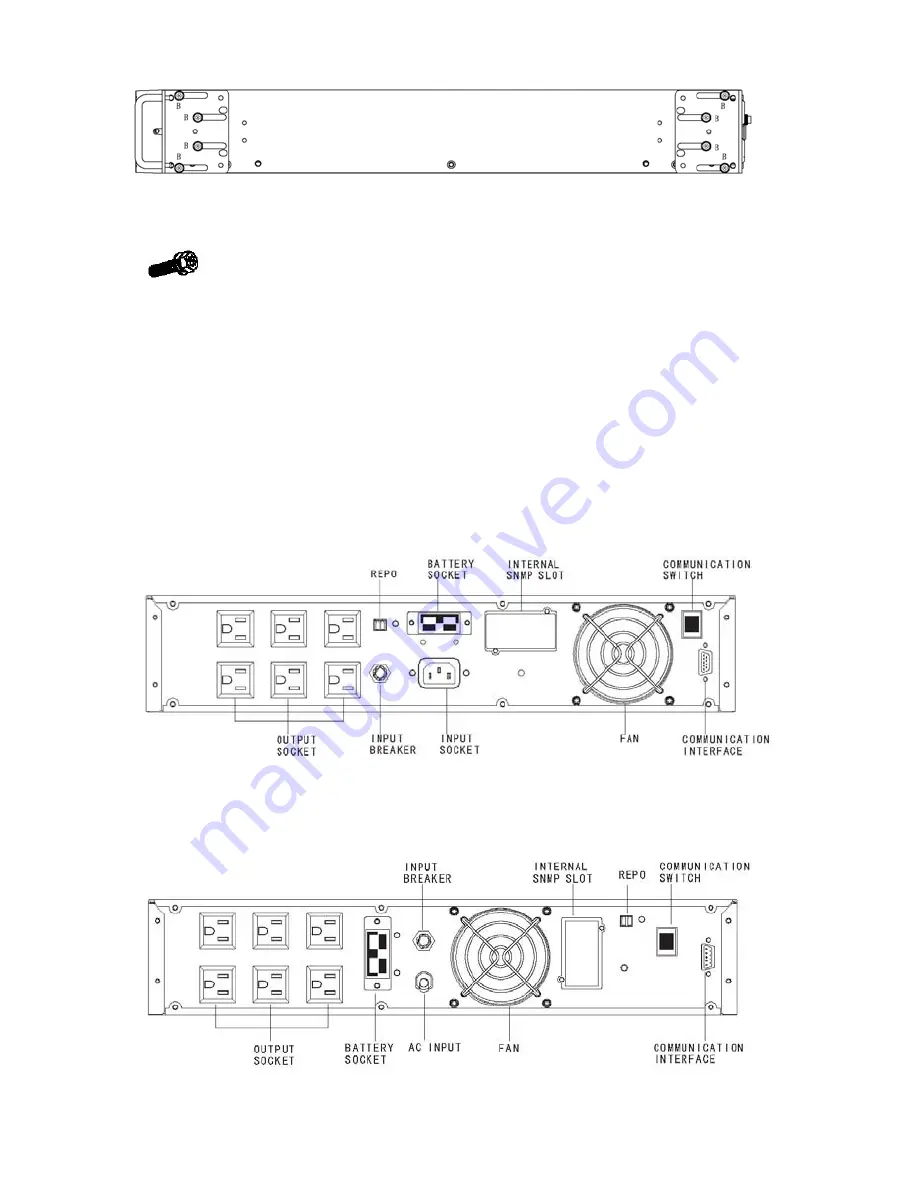
5.2 Rear Panel Views 


Fig. 2    1KVA REAR PANEL (Rack-mount)   


Fig. 3    1.5KVA REAR PANEL (Rack-mount) 


Summary of Contents for Network Xtreme Rack/Tower Series

Page 1: ...I Network Xtreme Rack Tower Series NXRT 1000 VA 3000 VA UPS User s and Installation Manual...

Page 2: ...or television reception is found to be influenced by harmful interference from the equipment it is recommended to use one of the following preventive measures Place the receiving antenna in a separat...

Page 3: ...larm connections 12 6 1 RS 232 Standard Interface port 11 6 2 Net communication SNMP card option 11 6 3 REPO port emergency power off 12 7 User s guide to operations 14 7 1 Starting and shutting down...

Page 4: ...y may explode CAUTION Do not open or mutilate the battery released electrolyte is harmful to the skin and eyes CAUTION A battery can present a risk of electric shock and high short circuit current The...

Page 5: ...cing on this equipment must be carried out by qualified service personnel Before conducting any maintenance repair or shipment first ensure that everything is turned off completely and disconnected Fo...

Page 6: ...ioners and vending machines among others So protection of sensitive electrical equipment is vital to protect against power outages low or high voltage slow voltage fluctuations frequency variations di...

Page 7: ...management system always monitors the conditions of the batteries sends any forewarnings if replacement is needed Otherwise every 30 days of normal mode operation a battery discharge test is performed...

Page 8: ...tem shall dictate the output power rating VA Allow a margin for future expansion or calculation inaccuracies from measuring power requirements Backup time required will determine the battery size need...

Page 9: ...l hazards may be fatal so keep this manual for all future reference WARNING It is strongly advisable not to open the UPS cabinet as the components have very high voltage and touching them may be fatal...

Page 10: ...requirements are met according to these technical specifications otherwise the safety of installation personnel cannot be guaranteed and the unit may malfunction Ensure that you remember the followin...

Page 11: ...s with Multi Use Brackets 19 Rack mount Installation 1K 1 5K UPS Batter pack Note Fix a M4 6 screw on four places marked with letter A 2K 3K UPS Batter pack Note Fix a M4 6screw on four places marked...

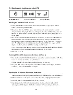
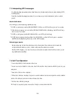
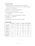
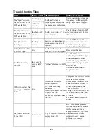
Page 12: ...7 23 Rack mount Installation Installations with Multi Use Brackets Tower Installation...

Page 13: ...8 Wall Mount Installtion Installations with Multi Use Brackets 4 Bracket 19 Rackmount Installtion...

Page 14: ...9 Note Fix a M5 10 screw on eight places marked with letter B Appearance dimension of M5 10 screw 5 2 Rear Panel Views Fig 2 1KVA REAR PANEL Rack mount Fig 3 1 5KVA REAR PANEL Rack mount...

Page 15: ...10 Fig 4 2KVA REAR PANEL Rack mount Fig 5 3KVA REAR PANEL Rack mount...

Page 16: ...the other end to a grounded outlet The batteries will automatically charge when connected to the mains Please realize that although you may start using the UPS immediately maximum back up time will st...

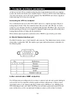
Page 17: ...Instructions provided in the power management software will help with this installation Other advanced power protection solutions such as SNMP are provided by your dealer 6 1 RS 232 Standard Interface...

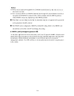
Page 18: ...of equipment the ground of each equipment should be shared The SNMP card is configured as DHCP by default IP setting Refer to the SNMP card manual how to find the card s IP and change the setting 6 3...

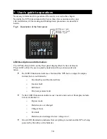
Page 19: ...ickly understand if any action needs to be taken Red LED illumination indicates a fault and the UPS has no output Examples include but are not limited to o Overload beyond the allowed time o Inverter...

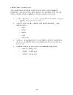
Page 20: ...The numerical data corresponds to the applicable category in line one and two Line Two Allows the user to identify which variable information is being displayed such as o Input o Output o Battery o Lo...

Page 21: ...LCD displays on line and means UPS is working in utility mode The UPS should now start its inspection of internal functions main synchronization and inverter startup Then power should start to be sup...

Page 22: ...display information This indicates the unit has no output 7 2 Self Test Operation Please refer to the three operating buttons on the front panel Confirm that UPS is in Utility Mode Press and hold the...

Page 23: ...he UPS will give a constant audible alarm displaying the cause on the LCD display Silencing an alarm By pressing any of the three buttons on the front panel the alarm can be turned off except when the...

Page 24: ...attention Several fault indicators and status indicators on is to help the user to diagnose fault When you contact service personnel the following information is required UPS MODEL No and SERIAL NO Da...

Page 25: ...tripped Reset circuit breaker Insufficient battery run time Once every 4 seconds in DC mode On batt displayed on LCD 1 If batteries are undercharged let UPS charge batteries at least 12 hours 2 After...

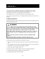
Page 26: ...ings 2 Use tools that have insulated handles 3 Keep tools and other metal objects from contacting and away from the batteries ELECTRIC ENERGY HAZARD Do not attempt to rewire alter or change any batter...

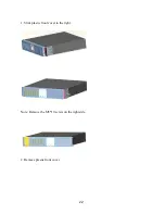
Page 27: ...22 1 Slide plastic front cover to the right Note Remove the M5 10 screw on the right side 2 Remove plastic front cover...

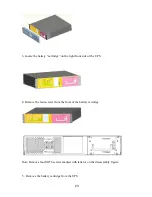
Page 28: ...tridge on the right front side of the UPS 4 Remove the four screws from the front of the battery cartridge Note Remove four M4 6 screws marked with letter A on the disassembly figure 5 Remove the batt...

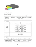
Page 29: ...XRT 3000 Voltage Range Single Phase When load 60 Input voltage range is 55 V 138 5V When 60 load 70 Input voltage range is 60 5V 138 5V When 70 load 80 Input voltage range is 70 5V 138 5V When load 80...

Page 30: ...near load 5 8 Output 110Vac THD Full load Non linear load 10 Output 115 120Vac Overload 108 150 30s transfer to by pass 150 200ms transfer to by pass Crest ratio 3 1 max Output waveform Standard sine...

Page 31: ...ss B Where and when the unit was purchased C All of the model information about your UPS D Any information on the failure including LEDs that may not be illuminated E A description of the protected eq...

Page 32: ...ef description of the problem 5 Mark the RMA on the outside of all packages The factory cannot accept any package without the RMA marked on the outside 6 Return the UPS by insured prepaid carrier to _...

Page 33: ...s of fact or promises by Xtreme Power for the products their merchantability or fitness for any particular purpose In no event shall Xtreme Power be liable for lost profits goodwill or any other speci...

Page 34: ...ipped from a Distributor or a Reseller the warranty period begins 60 days from the date of shipment from Xtreme Power If a Xtreme Power product is found to be defective Xtreme Power will at its sole d...

Reviews: