VESDA-E VES-A10-P Product Guide
100
www.xtralis.com
7.8
Replacing the Ultrasonics Flow Sensing and Scanning
Module
Caution:
Electrostatic discharge (ESD) precautions need to be taken prior to removing the fascia from
the detector. A wrist strap must be connected to the case of the detector (Figure 7-7).
To replace the Ultrasonics Flow Sensing and Scanning Module, perform the following steps:
1. Open the front door and remove the front fascia. Refer to Sections 7.2 and 7.4 for further information.
2. Take the top cover off. To do this, press the tabs down while pushing the cover from inside the detector.
3. Remove the Aspirator as described in Section 7.5 on page 88.
4. Remove the Sampling Module as described in Section 7.7 on page 95.
5. Remove Smoke Detection Chamber as described in Section 7.6 on page 90.
6. Remove Ultrasonics Flow Sensing and Scanning Module as described below.
7. Install the new Ultrasonics Flow Sensing and Scanning Module as described below.
8. Reinstall the Smoke Detection Chamber as described in Section 7.6 on page 90.
9. Reinstall the Sampling Module as described in Section 7.7 on page 95.
10. Reinstall the Aspirator as described in Section 7.5 on page 88.
11. Reinstall the top cover.
12. Reinstall the front fascia. Refer to Sections 7.2 and 7.4 for further information.
Remove the Ultrasonics Flow Sensing and Scanning Module
1. Turn off the 24V DC power to the detector.
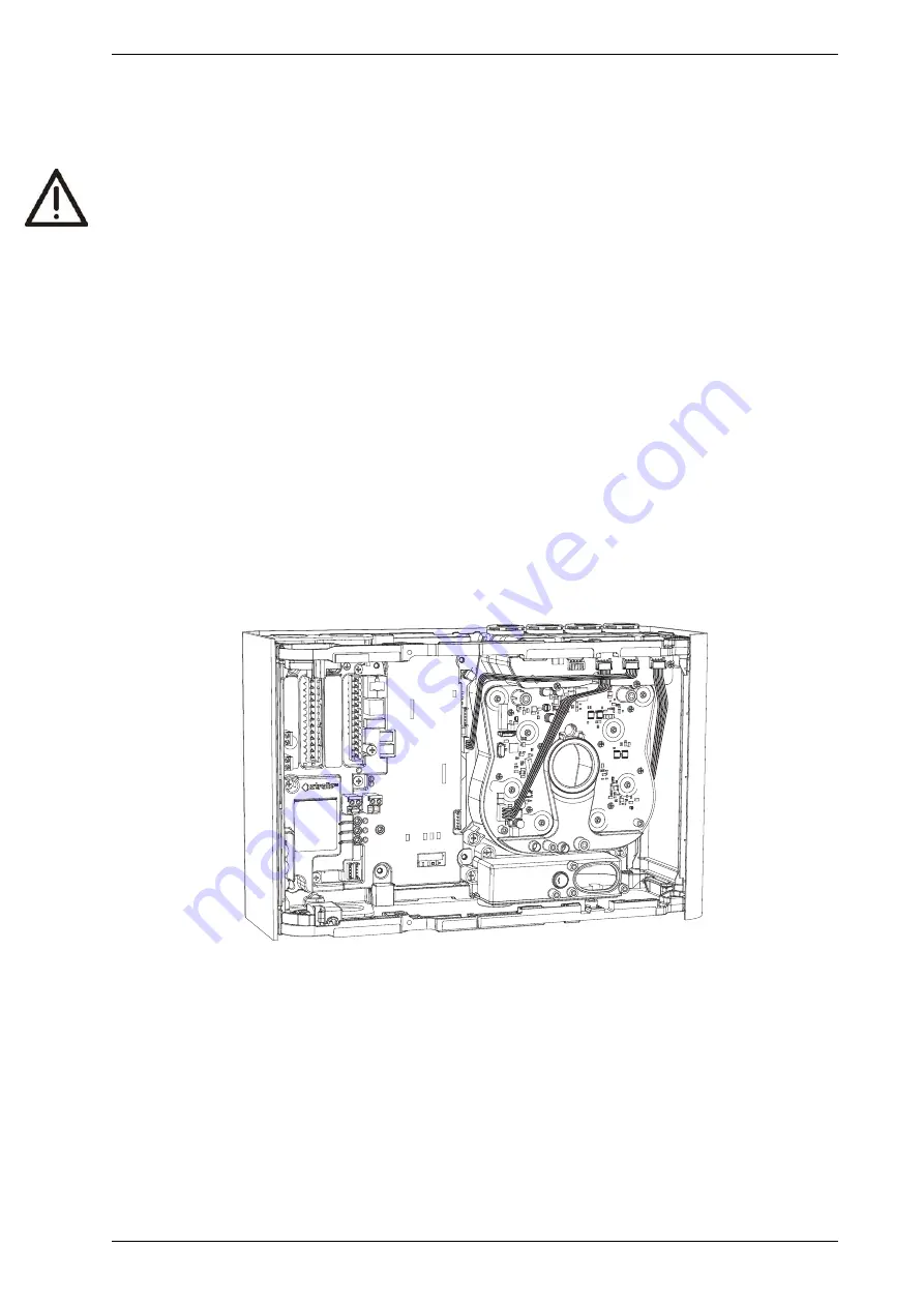
2. Disconnect the main board loom connection at J2 and antenna connection at J11 (Figure 7-24).
Figure 7-24: Disconnect the main board loom connection at J2 and antenna connection at J11
3. Remove the three screws holding the Ultrasonics Flow Sensing and Scanning Module to the detector
base (Figure 7-25).
Summary of Contents for VESDA-E VES-A10-P
Page 2: ......
Page 10: ...VESDA E VES A10 P Product Guide 4 www xtralis com This page is intentionally left blank ...
Page 22: ...VESDA E VES A10 P Product Guide 16 www xtralis com This page is intentionally left blank ...
Page 52: ...VESDA E VES A10 P Product Guide 46 www xtralis com This page is intentionally left blank ...
Page 82: ...VESDA E VES A10 P Product Guide 76 www xtralis com This page is intentionally left blank ...
Page 86: ...VESDA E VES A10 P Product Guide 80 www xtralis com This page is intentionally left blank ...
Page 103: ...VESDA E VES A10 P Product Guide www xtralis com 97 Figure 7 21 Undo Sampling Module screws ...
Page 108: ...VESDA E VES A10 P Product Guide 102 www xtralis com ...
Page 110: ...VESDA E VES A10 P Product Guide 104 www xtralis com This page is intentionally left blank ...
Page 114: ...VESDA E VES A10 P Product Guide 108 www xtralis com This page is intentionally left blank ...
Page 120: ...VESDA E VES A10 P Product Guide 114 www xtralis com This page is intentionally left blank ...
Page 126: ...VESDA E VES A10 P Product Guide 120 www xtralis com Z zone 57 58 81 115 ...


