Xtralis ICAM
Xtralis ICAM Communications Guide
www.xtralis.com
9
Each IFT detector is given a Modbus address from 1 to 16 and each RDU is given a matching address
from 1 to 16 and put into Multi-Master mode.
The RDUs will then poll their corresponding IFT detector and show any alarm conditions, faults and
smoke levels.
The corresponding detector will detect if a user presses the Reset or Isolate buttons on an RDU.
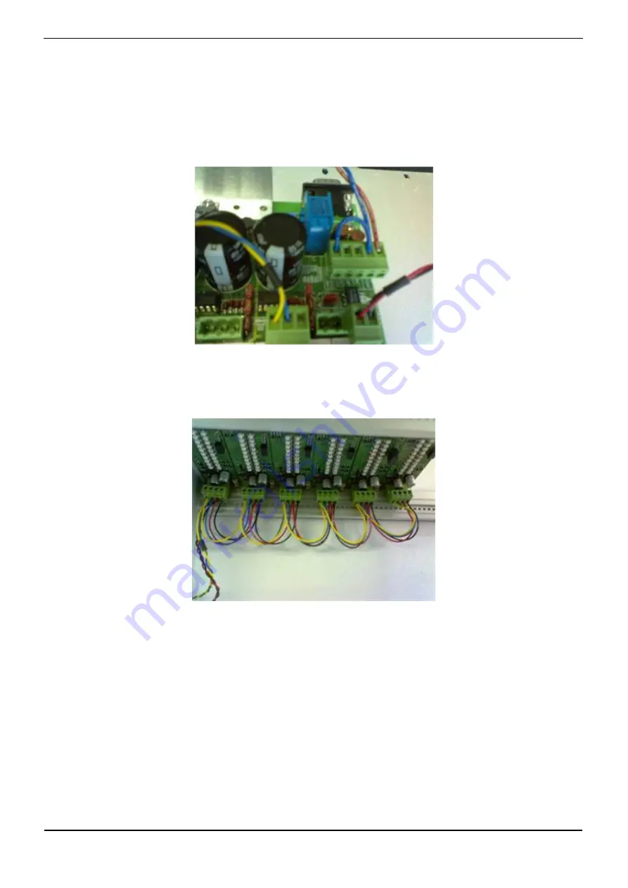
Wiring Connections
The above shows the wiring connections for the MqBridge.
•
Red/Blue
- Power-In to MqBridge (0 V, 24 V)
•
Blue/Yellow
- RS485 communications to Panels.
•
Black/Red
- Power-Out to Panels (0V, 24 V)


