2.1.4.
Multi-interfaces model
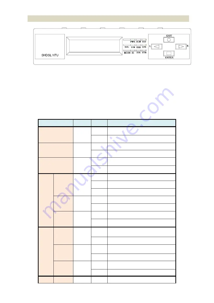
Front panel can be separated into three parts: LCD display, LED indicator and Keypads.
The LCD display can show the status and configuration of the device. The local management interface will be done by
keypad with this LCD display.
The purpose of the keypad is to configure the setting or function selection on this NTU.
The following table describes the LEDs’ functions of the SHDSL.bis NTU:
LED
Color
Action
Description
PWR
Green
On
Power is on.
Off
Power is off.
ALM
Red
On
System loss.
Off
System is working nomarally.
TST
Yellow
On
System is testing for connection.
Off
System is working nomarlly.
SHDSL
SYN
Green
On
SHDSL line is connected.
Blink
Data transmit in SHDSL line.
Off
SHDSL line is dropped.
ERR
Red
Blink
Error second occurs.
Off
No error second.
LPB
Yellow
On
Loopback is on.
Off
Loopback is off.
E1
SYN
Green
On
E1 line is connected.
Off
E1 line is dropped.
ERR
Red
Blink
There are error seconds.
Off
There is not any error second.
LPB
Yellow
On
Loopback is on.
Off
Loopback is off.
V.35
TD
Green
On
Data transmit in V.35.
Summary of Contents for G.SHDSL .bis NTU Series
Page 1: ...G SHDSL bis NTU XL GDB 102Ev3 User Manual Version 0 08 ...
Page 9: ...1 3 Applications ...
Page 23: ...2 3 1 E1 T1 Interface AC power input version DC power input version ...
Page 24: ...AC DC dual power input version Use DC input only ...
Page 25: ...2 3 2 Serial Interface AC power input version DC power input version ...
Page 26: ...AC DC dual power input version Use DC input only ...
Page 27: ...2 3 3 Ethernet Interface AC power input version DC power input version ...
Page 37: ......
Page 40: ...3 4 1 Show Statistic on E1 Interface ...
Page 41: ...3 4 2 Show Statistic on Serial Ethernet T1 Interface ...
Page 42: ...3 5 Menu tree for SYSTEM SETUP You can setup 11 interface modes via LCD display ...
Page 50: ...3 5 4 Sub Menu tree for SETUP SERIAL Interface SYSTEM SETUP SETUP SERIAL ...
Page 74: ...For Serial interface model For Ethernet interface model ...
Page 75: ......
Page 76: ......
Page 84: ...Menu tree The item according to which interface modes you have setup ...
Page 86: ...5 4 1 Configure NTU Interface Setup Interface ...
Page 134: ...For Ethernet interface mode For E1 and Serial interface mode ...
Page 136: ...For E1 interface mode For T1 interface mode ...
Page 137: ...For Serial interface mode For Ethernet interface mode ...
Page 138: ...For E1 Serial interface mode For E1 Ethernet interface mode ...
Page 141: ...When it is upgrading you can see the following ...
Page 147: ...The new login screen will be shown again you can type username and password again to enter ...
Page 152: ...The front view of DB 25 F Serial interface connector on rear panel ...
Page 154: ......


