background image

EX-SDI DVR OPERATION MANUAL


- 17 - 


Video detection alerts before you do the following steps:


Step 1: 

"main menu" > "system setting" > "alert configuration" > "video test", enter the video detection interface, as 

shown in Figure 11; 

Step 2: 

Select channel 1, check the dynamic test, adjustment the sensitivity level; 

Step 3: 

Setting the monitoring area, click on the "locale" SETTINGS, press and hold down the left mouse button and 

drag the mouse to the area delineated and can be used multiple times to delineate, delineating right-mouse, returns to 

the previous level, exit the Setup interface; 

Step 4: 

Click on the "treatments", entering the arming time interface, set the alarm time period. 

Step 5: 

Setting when the alarm status appears, this machine uses the linkage settings, and treatments. The linkage 

settings are: PTZ video channel linkage, linkage, loop (single frame loop selected pages) and grab; disposition: alarm 

output, screen tips, send EMAIL (required in the "advanced network", set EMAIL parameters) and buzz (buzz 

locally); 

Step 6: 

According to step two to step five, setting alarm parameters for other channels, in addition, the same 

parameters are available through the "copy" button to set; Note: video loss with video detection and alarm settings for 

the input method. 


12 PTZ Control


By following these steps, you can make simple pan/tilt control. 

Step 1: 

in the 

[main menu]

[PTZ Configuration]

, sets the basic parameters such as channel, agreements; Second 

Step 2: 

in the preview mode, enter the PTZ control window; 

Step 3: 

click sets the Protocol of the channel window, and click the right mouse button, select the PTZ control, enter 

the PTZ General function to control. You can also select high speed PTZ, hold down the right mouse button, you can 

directly manipulate PTZ, mouse move direction controllable pan/tilt position, using pulleys to control the zoom of the 

camera. 

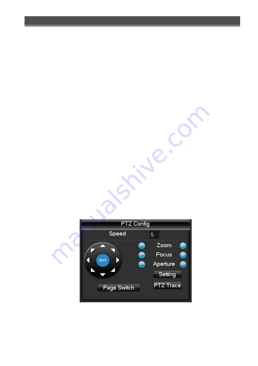
[Page Switch]: 

Tap to switch PTZ setting into the 

[accessibility] 

and 

[preset] 

function settings menu. 


Figure 1-15 

[Setting]: 

click on the PTZ control menu 

[setting] 

button to enter the PTZ Setup interface, as shown in the figure, 

set 

[preset]

[cruising]

[patrol trails]

[linear border] 

and so on. When does not support certain functions, menu  is 

shaded and cannot be selected. 

Summary of Contents for DVR-HXx92

Page 1: ...DVR HXx92 EX SDI video recorder user manual...

Page 2: ...a place of humidity dust or soot Please install this product horizontally and guard against falling for this product Please install in a well ventilated place do not block the airflow to the device Pl...

Page 3: ...Configuration 9 7 Video Plans 11 8 Video Search 12 9 Video Backup 14 10 Network Configuration 15 11 Alarm Settings 16 12 PTZ Control 17 13 Voice Talkback 19 PART 2 PC REMOTE MONITORING 20 1 PC Remote...

Page 4: ...ing modes support SATA hard drive and local hard S MA R TR technology equipped with USB interface for backup of local drive or network function Playback Functions Can realized by multiple criteria in...

Page 5: ...rd disk recommended by the manufacturer suitable for DVR hard drive After booting the system will automatically format the hard disk and original data on your hard disk may be completely lost Hard dis...

Page 6: ...to the system you pop up a password entry box During real time monitoring click the left button to enter the main menu If user didn t login yet pop up oflogin interface will come out When the cursor...

Page 7: ...ack and forth to change the effect of PTZ 3D zoomfunction Mouse movement Select the current coordinate control or control a particular move Mouse drag Marquee motion detection area Marquee locale regi...

Page 8: ...use other types of branded power supply instead of the original power supply 1 6 Shutdown Turn off the device soft and hard switches Soft switch go to main menu shut down the system select close hard...

Page 9: ...Enable box unchecked Enabled box is checked state Transferred out of the drop down menu Determined to modify the settings menu to enter Set cancel to cancel the change to enter the menu To set the par...

Page 10: ...ncorrectly for continuous 5 times After 30 minutesor reboot the DVR system will be unlocked by itself For security the password should be modified as soon asyou first using the DVR 3 preview Device bo...

Page 11: ...ttings normal motion detection and alarm the video type and video recordingtime Manual no matter what channel is currently in a State select manual the corresponding channel fullmanual video Off no ma...

Page 12: ...ength You can set the length of each video files the default is 60 minutes a maximum of 120minutes DVR NO It is used more than a remote control or control panel remote control DVR only when I press th...

Page 13: ...ize Select the CIF resolution shots Picture Quality 6 speed can be set respectively for the low low low medium high and maximum Snapshot Frequency Setting the single channel maximum shot frequency 2 r...

Page 14: ...ds of color display the corresponding channel a week ordinary dynamic detection and alarm three video state of time plan can be in click on each date corresponding Configuration modified Copy Configur...

Page 15: ...rdingeffective 8 Video search From Shortcut Menu search go into the playback interface Player toolbar instructions Graph 1 2 Button Instructions Play pause key Every time you play this backwards back...

Page 16: ...e playback pause playback status implemented Special Features Playback When single screen preview or playback in full screen can be press the left key of mouse to choose any size area in screen pictur...

Page 17: ...1 10 Detection When you insert a USB external storage device can detect whether the USB device is correctly identified If identified correctly the list should be displayed in the corresponding device...

Page 18: ...start the system will automatically start the video files are backed up and shows the time remaining Note Video files after backup to a USB drive the automatically be carried to the player you can cl...

Page 19: ...network to a remote image monitoring equipment public network setting to reference the part 2 of the PC remote monitoring 11Alarm Alarm configuration includes the local alarm detection and video detec...

Page 20: ...Step 6 According to step two to step five setting alarm parameters for other channels in addition the same parameters are available through the copy button to set Note video loss with video detection...

Page 21: ...nt function is part of the Protocol is not supported Tour Traces settings click tour traces button as figure by shows and will this a process records of for tour traces x again click page Switch butto...

Page 22: ...on please refer to the corresponding product specification table 13 2 Intercom Configuring DVR locally configure the microphone connected to the MIC on embedded DVR audio input port audio output termi...

Page 23: ...router mappings A device mapping Sign in to the router go to forwarding rule DMZ host start the DMZ host the DMZ host IP address is the IP address of theDVR Multiple devices mapping Sign in to the rou...

Page 24: ...ddress bar make the connection After a successful connection will pop up interface as shown below Figure 2 1 Note We recommend using the PC s browser If prompted to install the ActiveX control please...

Page 25: ...n Enter your user name and password company factory default administrator username is Admin and no password Asking the user to change the administrator password after login After a successful login di...

Page 26: ...ch as local DVR configuration operation instructions on the DVR as the PART 1 localof basic operation Figure 2 4 3 2 Screen spilt Select the preview screen mode as shown in Figure 15 the nether button...

Page 27: ...he channel s all off button formerly the open all button video all open into a closed or click on the lower right corner of the video area to close the channel video Video watch the lower left corner...

Page 28: ...dge Finish line sweep course settings Preset through direction buttons to turn the camera to the desired position preset input box enter the preset point values click the Add button tosave Cruise grou...

Page 29: ...query interface at the bottom shows the current download speed and progress 3 9 Alarm Configuration Click on the Alarm setting to enter the alarm setting menu you can make alarm setup and operation o...

Page 30: ...tralized management software distributed architecture set multi windows multi user multilingual talkback stand alone direct attached device functions such as monitoring system as awhole Friendly inter...

Page 31: ...ystem interface as shown in Figure 3 6 Through the System Setting Monitoring Management add Search add into the add device screen follow the prompts to add the DVR device information save and exit Ste...

Page 32: ...erface as shown following Figure3 3 enter your account number and password clicking information bar help OK to enter the system First time login system built inAdmin account have the device management...

Page 33: ...of equipment time and date display hard disk system information is displayed display area As shown in Figure2 13 Figure 2 13 4 4 1 Context Menu In real time view mode you can click the right mouse bu...

Page 34: ...ss Contrast Saturation Hue and Default Settings on the screen System Settings Management of Surveillance ADD Add surveillance device into surveillance management Change Modify the name of device Type...

Page 35: ...channel in the screen 2 4 Channel Pre view Button Click it to active the functions to show four real time channels in the screen 3 9 Channel Pre view Button Click it to active the functions to show n...

Page 36: ...igure 2 17 Figure 2 17 4 4 8 PTZ Control When network video surveillance serve successfully connect with speed dome cameras user can control the speed dome cameras in control center Through Upward Dow...

Page 37: ...surveillance area 8 Set the rotary speed of the cruise between presetting points When it is activated speed dome cameras will display each presetting points in turn The cruise of every presetting poin...

Page 38: ...uantity of channels in the device normally 4 8 16 for DVR and 1 for IP cameras IPAddress Set the IP address which used to be used in intranet connection Domain Name Set the domain name for this device...

Page 39: ...matically display the image of the channel in the video area which is shown as the following Figure 2 21 Modify Modify device Figure 2 21 After enter the surveillance point management click the device...

Page 40: ...shown in the following Figure 2 22 Figure 2 22 CMS Configuration Page including Local Storage Storage Settings Screenshot Settings and soon Storage Choose the HDD to store recording orimage Log Maint...

Page 41: ...screenshotimages Time Sync Adjust its time to be in accordance with user computer Version Information Display the version of CMS Languages Choose the languages of CMS Figure 2 23 4 5 3 Device Configu...

Page 42: ...t to make configuration The operationsof device configuration are the same with it in IEbrowser 4 5 4 User Management Please refer to the first partition DVR Local Basic Surveillance 4 5 5 PC Log Plea...

Page 43: ...ION MANUAL 40 4 7 Recording Function Click to unfold the interface of recording as shown in Figure 2 25 Figure 2 25 4 7 1 Recording Playback Click to enter the interface of playback as shown in Figure...

Page 44: ...nels that no need to display playback Step 2 choose the type of the recording file such as all recording Alarmrecording Step 4 choose the start time and end time of recording video Step 5 search recor...

Page 45: ...arately set save path of recording whether needs video loop packet size of recording recording time and recordingchannel It is shown as following Figure 2 27 Figure 2 27 User can set the pattern of re...

Page 46: ...ayback Support two way voice intercom Supports remote video playback Support for remote alarm function The following sections is the user manual will be Android version for example introduced the useo...

Page 47: ...ION MANUAL 44 Figure 3 1 Figure 3 2 3 Login Interface Run HDIVS client open the login screen as follows users need to log in account and user name is theemail address used when registering As shown in...

Page 48: ...een added Sign up process is simple enter the user s email address as shown in Figure 3 4 Figure 3 4 3 2 Watch Temporary HDIVS allows users to temporarily use one of watching a video you can directly...

Page 49: ...successful login HDIVS mobile client you can see the main screen will appear as shown in Figure 3 6 Figure 3 6 The black area in the Middle for video playback video playlist is divided into the privat...

Page 50: ...ice Management 4 1 Add Device Open the HDIVS the main menu device management in the private facility page click add as shown in Figure 3 7 Figure 3 7 HDIVS Add mode supports both IP and GID equipment...

Page 51: ...apping user name and password As shown in Figure 3 8 4 1 2 GID Mode The GID is factory configured to the equipment one by one user except in the packaging can find this information on the label HDIVS...

Page 52: ...into QR code scanning mode at the QR code labels on the equipment housing the factory Gets the GID UUID number into a network camera as shown in Figure 3 11 and Figure 3 12 Figure 3 11 Figure 3 12 By...

Page 53: ...k cameras GID number in the network as shown in Figure 3 13 and Figure 3 14 Figure 3 13 Figure 3 14 4 2 Alarm Information Setting If the front end device has been started up alarm arming users can HDI...

Page 54: ...en the HDIVS the main menu device management in the private facility on the page select the device you want to remove and on the device information page click on the upper right corner of the Edit but...

Page 55: ...EX SDI DVR OPERATION MANUAL 52 Figure 3 16 1 2 3 4...

Page 56: ...device name prefix dot is green the table of equipmentonline Conversely if displayed as a red it means that the device is offline Click on device name video mobile client that will be connecting to th...

Page 57: ...ilt digital zoom and image response As shown in Figure 3 19 and Figure 3 20 1 PTZ Direction Control Figure 3 19 2 Digital Zoom Figure 3 20 4 4 2 Buttons Description In landscape mode tap the screen mo...

Page 58: ...ATION MANUAL 55 Figure 3 21 Buttons Icon Buttons Function Share Select video quality level Capture Local Recording Listening Talkback Zoom In Zoom Out IRIS Increase IRIS Reduce Focus Increase Focus Re...

Page 59: ...ved alarming information 4 6 Capture File Manager 4 6 1 Browse File Open the HDIVS mobile main menu video capture file and enter capture pictures and video files page userscan choose to open the corre...

Page 60: ...heoperation Remove all click on the page empty eject the empty prompt dialog box select OK then empties all of the page file or folder click Cancel to quit the operation As shown in Figure 3 23 Figure...

Page 61: ...EX SDI DVR OPERATION MANUAL 58 Figure 3 24 Figure 3 25 Figure 3 26...

Page 62: ...PS 1080P 120FPS 720P 240FPS Decode 1080P 60FPS 720P 120FPS 1080P 120FPS 720P 240FPS Video Input SDI 1080P 500M TRANSFER Output 1 HDMI with Audio and 1 VGA 1 Main BNC for D1 Audio Input 4 RCA 4 RCA Out...

Page 63: ...al cable with BNC connectors cable harness standard model ND5C 2V 750hm 75 5 Hard Disk Capacity Computation Initial setup of DVR make sure the hard drive is mounted in the machine Size recorders for a...

Reviews: