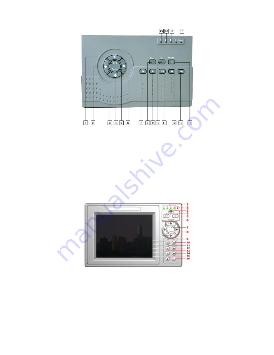
background image


                                                                                                                                      8      


Figure 1-1 

1. Upper                        2.Left                              3. Esc  
4. Down                         5.Enter                           6. Right    
7. Previous                    8. Record                       9.Slow play  
10. Assistant                 11. Play/Pause              12.Fast forward  
13. Next                         14. On/off                      15.The first channel indication light   
16. The second channel indication light               17. The third channel indication light    
18 Power indications light  
 
The other front panel is shown as in Figure 1-2. 


Figure 1-2 

1. Record indication light                                  2.Power indication light        
3. Remote control signal receiver                     4.Switch button  
5. Power button                                                 6. Direction buttons/1.2.3.4 
7. Esc                                                                8.Enter  
9. Backward play/Pause/5                                10.Play/Pause/6 
11. Slow play/7                                                 12.Forward/8 
13. Previous/9                                                   14.Next/0 

Summary of Contents for DVR-475EL

Page 1: ...1 DVR 475EL Standalone DVR Quick User s Manual...

Page 2: ...s 12 1 5 2 Relay Output Description 14 2 Overview of Navigation and Controls 15 2 1 Login Logout Main Menu 15 2 1 1 Login 15 2 1 2 Main Menu 15 2 1 3 Logout 16 2 1 4 Auto Resume after Power Failure 16...

Page 3: ...3 4 8 2 PTZ Setup 24 4 8 3 3D Intelligent Positioning Key 26 3 Web Client Operation 27 3 1 Network Connection 27 3 2 Login 27 3 3 Main Window 28...

Page 4: ...in a very short time Here you can find hardware installation cable connection information and general operations such as system setup record search backup alarm setup also here you can find web operat...

Page 5: ...ineers We are not liable for any problems caused by unauthorized modifications or attempted repair 5 Environment The DVR should be installed in a cool dry place away from direct sunlight inflammable e...

Page 6: ...can use 120G 750G HDD to guarantee higher stability The formula of total HDD size is Total Capacity MB Camera Amount Recording Hours HDD Usage Per Hour M h H 264 compression is ideal for standalone D...

Page 7: ...cable to SATA port 8 Connect power cord to the HDD 9 Place the unit cover back and screws firmly After HDD installation please check connection of data ribbon and power cord 1 3 Front Panel This secti...

Page 8: ...d channel indication light 17 The third channel indication light 18 Power indications light The other front panel is shown as in Figure 1 2 Figure 1 2 1 Record indication light 2 Power indication ligh...

Page 9: ...o to the next menu item In numeral input mode click this button to input 5 15 Record REC Working with direction keys to enable disable record 16 Assistant Fn In 1 window display mode click this button...

Page 10: ...tch PTZ control In numeral input mode Click to input 8 1 4 Rear Panel 1 4 1 Overview Please refer to Figure 1 3 for MB D AL series DVR real panel information Figure 1 3 1 Power socket 2 Power button 3...

Page 11: ...video inpu channel 6 The first audio input channel 7 The first video input channel 8 Audio output 9 Video output 10 VGA port 11 RS232 port 12 USB port 13 Networkport RJ45 14 ALARM RS485 port 15 Power...

Page 12: ...series DVRs have two alarm types Normal open NO and normal close NC 1 5 1 Alarm Input and Output Details Please refer to Figure 1 6 for AG AH series alarm input and output information The alarm gets a...

Page 13: ...t it to the alarm device power below 1A A B is A cable and B cable to control 485 device You can connect them to devices such as decoder Please parallel connect a 120 resistance if there are too much...

Page 14: ...und of the alarm detector Please connect the NC port of the alarm sensor to the DVR alarm input ALARM If you need to reset the touched off alarm remotely you can use DVR to supply controllable 12 V po...

Page 15: ...an only monitor playback backup and etc Username default Password default hidden user For your system security please modify you password after first login You can use USB mouse front panel remote con...

Page 16: ...utton on the front panel for at least 3 seconds system will stop all operations Then you can click the power button in the rear panel to turn off the DVR 2 1 4 Auto Resume after Power Failure The syst...

Page 17: ...in default 24 hour regular mode You can set record type and time in schedule interface 2 3 1 Schedule Menu In the main menu from setting to schedule you can go to schedule menu See Figure 2 5 There ar...

Page 18: ...menu There are two ways for you to go to manual record menu Right click mouse or in the main menu Advanced Manual Record In live viewing mode click record button in the front panel or record button i...

Page 19: ...privacy mask zone can not be view by the user when system is in monitor status Time display You can select system displays time or not when you playback Channel display You can select system displays...

Page 20: ...trol Click search in the main menu Search interface is shown as below See Figure 2 10 Usually there are three file types R regular recording file A external alarm recording file M motion detection rec...

Page 21: ...Volume 9 Previous file 10 Next channel 11 Next file 12 Previous channel 13 Search 14 Backup 2 3 6 Basic Operation 2 3 6 1 Playback There are various search modes video type channel number or time The...

Page 22: ...back function Button Illustration Remarks Fast play button In playback mode click this button to switch between various fast play modes such as fast play 1 fast play 2 and more Fast play 1 means fast...

Page 23: ...unter clock wise to view I frame playback Note All the operations here such as playback speed channel time and progress have relationship with hardware version Some series DVRs do not support some fun...

Page 24: ...ome RS485 port to DVR 485 port Connect dome video output cable to DVR video input port Connect power adapter to the dome 4 8 2 PTZ Setup Note The camera video should be in the current screen Before se...

Page 25: ...none Default setup is none Figure 2 13 After all the setting please click save button In one window display mode right click mouse click Fn Button in the front panel or click Fn key in the remote con...

Page 26: ...of the eight direction arrows there is a 3D intelligent positioning key See Figure 2 17 Click this key system goes back to the single screen mode Drag the mouse in the screen to adjust section size It...

Page 27: ...account control After completing setup please reboot the PC System can automatically download latest web control and the new version can overwrite the previous one If you want to un install the web c...

Page 28: ...nterface is shown as below See Figure 3 3 Please input your user name and password Default factory name is admin and password is admin Note For security reasons please modify your password after you f...

Page 29: ...ote current preview window is circled by a green rectangle zone Section 5 Here you can view window switch button You can also select video priority between fluency or real time System monitor window s...

Page 30: ...eration under your name For detailed operation introduction please refer to our resource CD included in your package for electronic version of the user s manual Slight difference may be found in user...

Reviews: