background image


25   


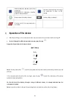
Recall Memory 


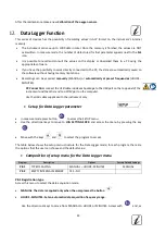
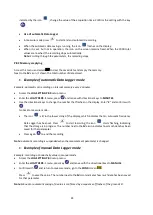
In measure mode in the parameter of interest, press key 

  to enter the RECALL MEMORY mode. 

The last saved data is shown on the display. 


As indicated by the string 

, use the directional keys to scroll through the different stored values. 

The number next to the 

M+

 icon indicates the save slot. 


Press 

 to return to measure mode. 


Note

: if during the data saving, the instrument is in error, this error will be displayed on the data recall phase 

on the instrument 


Clear the saved data 


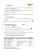
 To clear the data stored in the instrumental memory, access the 

CLEAR DATA P8.2

 setup menu and 

select 

YES


IMPORTANT

: Factory reset of the pH, ORP and Cond parameters does not delete the stored data 


Instrument Setup menu   


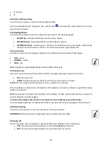
In measure mode, press key 

 to access the SETUP menu. 


Use the directional keys to move to 

SETTINGS P9.0

 and access the menu by pressing the key 

 . 


Move with the keys 

 and  

 to select the program to access. 


The table below shows the setup menu structure for the general settings of the instrument; for each 

program, there are the options that the user can choose and the default value: 


Composition of the setup menu for Setting menu 


Program 

Description 

Options 

Factory Default 

Settings 

P9.1 

TEMPERATURE U.M. 

°C / °F 

°C 

P9.2 

DATE AND TIME SET 

P9.3 

BACKLIGHT MODE 

INDOOR – OUTDOOR-AUTOMATIC 

AUTOMATIC 

P9.4 

BRIGHTNESS 

LOW – MEDIUM - HIGH 

MEDIUM 

P9.5 

SLEEP MODE 

OFF – 2 MIN – 5 MIN 

2 MIN 

P9.8 

RESET 

YES - NO 

NO 

P9.9 

AUTO POWER-OFF 

YES – NO 

NO 


P9.1 Unit of measurement for temperature 

Access this setup menu to select the temperature unit to use: 

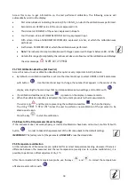
Summary of Contents for OXY 70

Page 1: ...1 Rev 1 0 26 02 2020 EN OXY 70 Vio INSTRUCTIONS MANUAL O2 mg l mbar Temp...

Page 2: ...2 Rev 1 0 26 02 2020 EN...

Page 3: ...eyboard 10 LED 10 Installation 10 Supplied components 10 Start up 11 Connection of the power supply 11 Power on date and time update power off 11 Replacement of batteries 12 Instrument transportation...

Page 4: ...ophore 22 Data Logger Function 23 Setup for Data Logger parameter 23 Composition of setup menu for the Data Logger menu 23 Example of automatic Data Logger mode 24 Example of manual Data Logger mode 2...

Page 5: ...olour LCD display shows all the necessary information such as the measurement the temperature the buffers used for the last calibration also custom the condition of stability Everyone can use these to...

Page 6: ...zardous situation which could lead to serious injury or death if not avoided ATTENTION for a dangerous situation with reduced risk which can cause material damage data loss or minor or medium sized ac...

Page 7: ...ular functionality of the device and the operator safety are guaranteed only if all the following indications are respected the instrument can be used in accordance with the specifications mentioned a...

Page 8: ...nd uses the tool or authorizes its use by other people is the owner of the tool and is responsible for the safety of all users of the tool and third parties The owner of the instrument must inform use...

Page 9: ...Sound level during standard operation 80 dB Environmental operating conditions 0 60 C Maximum permissible humidity 95 non condensing Maximum altitude of use 2000 m System dimensions 185 x 85 x 45 mm...

Page 10: ...ts The instrument is always supplied inside the specific carrying case with these accessories batteries adaptor 5V with USB cable standard 0 oxygen paper tissues screwdriver beacker multilingual user...

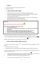
Page 11: ...by pressing the button The display initially activates all segments and then appears model and firmware of the instrument settings relating to the most important parameters and possible information a...

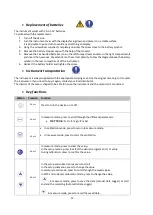
Page 12: ...original case only to transport the instrument If you need to buy it again contact your local distributor The interior of the case is shaped to be able to house the instrument and the sensors still c...

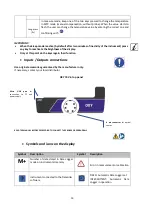
Page 13: ...he keys regain their function Inputs Outputs connections Use original accessories guaranteed by the manufacturer only If necessary contact your local distributor OXY 70 Vio top panel READ THE MANUAL B...

Page 14: ...n before turning off To scroll through the different parameter screens press the key Sequence of parameters in measure mode OXY 70 Vio O2 mg l mbar Note Pressing the button after the last parameter th...

Page 15: ...etup menu In measure mode press the key to enter SETUP mode select the parameter to edit by using the directional keys and confirming with OXY 70 Vio DO SETTINGS LOG SETTINGS SETTINGS Within the selec...

Page 16: ...Mode P9 8 Reset Settings P9 9 Auto Power Off Temperature measurement ATC MTC ATC The direct measurement of the sample temperature for all parameters is carried out through the NTC 30K probe integrate...

Page 17: ...TA P5 7 SET DUE CAL NO HOURS DAYS NO P5 8 RESET SETTINGS YES NO NO P5 9 TEMPERATURE CAL YES NO P5 1 Cal 0 Calibration with Standard Zero 02 Access this setup menu to select the calibration with Standa...

Page 18: ...nge the number that appears in the center of the display entering the hours or days that must elapse between two settings and confirm with If a calibration deadline is set the icon is present on the d...

Page 19: ...ght of blue colour that is reflected from the luminophore on an inner photocell When the oxygen permeating through the membrane comes in contact to the luminophore it modifies the blue light in propor...

Page 20: ...ore is replaced by a new one The probe is not used for a long period of time 3 6 months The instrument does not calibrate at 100 in this case calibrate it before at 0 The instrument does not measure c...

Page 21: ...sed for a long time After the luminophore replacement Errors during calibration NOT STABLE The button was pressed with still unstable signal Wait for the icon to appear to confirm the point WRONG BUFF...

Page 22: ...eading does not stabilize it is necessary to perform a maintenance of the probe in the following way 1 Check that the luminophore is clean in case wash it with water 2 The luminophore must be intact u...

Page 23: ...o the USB port on the top panel of the instrument and the other end to a COM port on the computer Use the USB cable supplied with the instrument only Setup for Data Logger parameter In measure mode pr...

Page 24: ...to MINUTES Use the directional keys to change the number that flashes on the display Enter 2 and confirm with Go back to measure mode The icon is lit in the lower string of the display which indicates...

Page 25: ...t delete the stored data Instrument Setup menu In measure mode press key to access the SETUP menu Use the directional keys to move to SETTINGS P9 0 and access the menu by pressing the key Move with th...

Page 26: ...after how long activating the device Sleep mode OFF Sleep mode off 2 MIN The instrument enters Sleep mode if no key is pressed for 2 minutes 5 MIN The instrument enters Sleep mode if no key is presse...

Page 27: ...switch on the instrument Wait for connection to be established the connection data are shown at the bottom left of the display Functions Download the data saved in the instrumental memory are downloa...

Page 28: ...ll repair or replace defective components This warranty does not apply if the product has been damaged used incorrectly exposed to radiation or corrosive substances if foreign materials have penetrate...

Reviews: