3
3.3 Enter/exit factory adjustment method
Use remote control, press “MENU” button, then press 6483,”TEST”will appear on screen to show that
you have entered the factory adjustment method, press “STANDBY” to exit it. Use factory remote control,
press the “PRESET” and “TEST” button, then the screen display “test” which means you have entered
into the factory adjustment mode, press the “TEST” or “STANDBY” to exit.
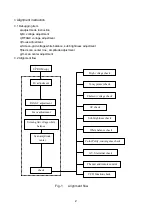
3.4 select adjustment item and adjust data
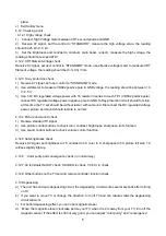
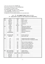
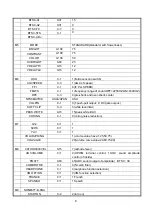
after entering factory adjustment mode, press 1-4 number buttons to select menu 1- menu 4; To enter
into MENU0, MENU5-MENU9, you may return to MENU1-MENU4 or just after you enter into “TEST”
interface, quickly press“CHILD LOCK” button and then the number button (0,5-9) to enter into relative
menus. Press “CH+” and “CH-” to select and “V+” and “V-”to adjust.
3.5 User purview
a).Factory adjustment mode menu1-menu4: only debugging worker, service checker, craftwork
technician, designer may operate.
b).Factory adjustment mode menu0, menu5-menu9: only craftwork technician, designer may operate.
4 Alignment method
4.1 B+ voltage adjustment
a) connect B+ point with a digital voltmeter to measure the negative pole of VD524
b) receive PHILIPS test pattern signal and set the picture to standard.
c) Adjust VR501 to let the value of B+ voltage be 110 V
±
0.5 V (yongxin super pure flat)
4.2 AGC adjustment
a) receive VHF-H band,60 dB RF signal.
b) Select factory menu2 of “AGC”.
c) Adjust AGC-TOP to let the picture just without noisy, then the voltage of tuner AGC is the
required value for adjustment.
d) exit factory menu
4.3 Normal temperature aging
a) do not receive signals.
b) under ”Test” condition, set the accelerator to an appropriate point for aging.
4.4 Accelerator adjustment
a) do not receive signals;
b) select “SC” of factory menu3 to let the field scanning stop working.
c) adjust acceleration potentiometer to let bright lines just appears on screen.
d) exit SC menu.
4.5 High voltage check
Note: the main power voltage (B+=110 V)can affect the high voltage directly, so be sure to let the B+
power voltage accurate. Under any state, the high voltage should not exceed 28 kV.
a) connect an accurate high voltage meter between the second anode cap of picture tube and
ground.
b) turn on TV and receive testing card signal.
c) set picture to standard, the high voltage should be 25 kV
±
0.5 kV.
d) the high voltage should not exceed 27KV with minimum brightness and contrast.
4.6 Focus adjustment
a) receive A12-PHILIPS (NTSC)signal
Summary of Contents for TK1433
Page 1: ...COLOR TELEVISION TK14 20 ...
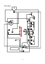
Page 17: ...15 Wiring diagram ...
Page 47: ...1 Exploded views TK1433 ...
Page 49: ...3 TK2026 1 2 3 4 5 6 7 8 9 10 11 12 13 14 15 16 17 18 19 20 21 22 23 24 25 ...
Page 51: ...5 TK2050 TK2051 ...
Page 53: ...7 TK2053 ...
Page 56: ......


