1
3
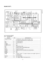
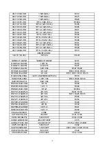
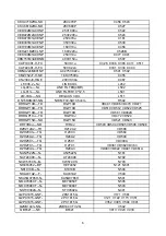
TV-processor (3.3 V)
VPE
55
OTP Programming Voltage
VDDC
56
digital supply to core (3.3 V)
OSCGND
57
oscillator ground supply
XTALIN
58
crystal oscillator input
XTALOUT
59
crystal oscillator output
RESET 60
reset
VDDP
61
digital supply to periphery (+3.3 V)
P1.0/INT1
62
TV/AV (AV1) / AV2 /S-VHS mode Output.
P1.1/T0
63
TV/AV (AV1) / AV2 /S-VHS mode Output.
P1.2/INT0
64
Remote control signal input.
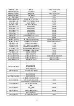
AN7522/AN17821A Function : audio output
Symbol
PIN
Function
Symbol
PIN
Function
Vcc 1
Power
supply GND
7 ground
Out 1 (+)
2
Ch 1 output (+)
In 2
8
Ch 2 input
GND(out 1)
3
Ch 1Ground
VOL
9
Volume Control
Out 1 (-)
4
Ch 1 output (-)
Out 2 (-)
10
Ch 2 output (-)
Standby
5
Mute input
GND(out 2)
11
Ch 2 Ground
In 1
6
Ch 1 input
Out 2 (+)
12
Ch 2 output (+)
STV9302A/LA78040 Function : vertical output
Symbol
PIN
Function
Symbol
PIN
Function
INV IN
1
Input
V OUT
5
Vertical output
VCC1 2
Power
VCC2 6
Output
power
supply
PUMP UP
3
Pump up power
NON INV IN
7
Negative feedback
GND
4 Ground
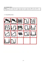
IC voltages
TDA(OM)8377
PIN 1 2 3 4 5 6 7 8 9 10
11
12
13
14
15
16
V 2.8 3.8 3.6 3.3 3.5 3.5
0.1
0.1
0 5.4
0.1
0 2.3 8 5 3
PIN 17 18 19 20 21 22
23
24
25
26
27
28
29 30 31
32
V 4 0 4 0.9
0.7
0.8
1.9
1.9
3.9
3.8
1.6
3.2
3.4 0 2.4
0.1
PIN 33 34 35 36 37 38
39
40
41
42
43
44
45 46 47
48
V 0.6 0.5 3.7 1.7 2.4 3.1
8 3.8
0 3.4
1.5
3.6
2.3 2.6 2.6
2.6
PIN 49 50 51 52 53 54
55
56
57
58
59
60
61 62 63
64
V 2.3 7.2 2.7 2.7 2.7 3.5
0 3.5
0.1
1.7
1.8
0 3.5 0.1 0.1
5
STV9302A/LA78040
PIN
1 2 3 4 5 6 7
V
0.7
15
-12
-15
0.3 15.9
-0.07
Summary of Contents for TK1433
Page 1: ...COLOR TELEVISION TK14 20 ...
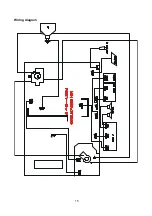
Page 17: ...15 Wiring diagram ...
Page 47: ...1 Exploded views TK1433 ...
Page 49: ...3 TK2026 1 2 3 4 5 6 7 8 9 10 11 12 13 14 15 16 17 18 19 20 21 22 23 24 25 ...
Page 51: ...5 TK2050 TK2051 ...
Page 53: ...7 TK2053 ...
Page 56: ......


