NOTE: Hand tighten bolts and locknuts until machine is fully assembled.
Lock nuts may require additional force to tighten completely.
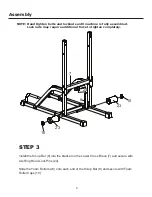
STEP 2
STEP 1
Assembly
Insert the bar on the Lower Support (4) into the
Left Base (2), securing with M8 x 20 Bolt (A6)
Insert the Lower Upright (6) into the Left Base (2)
securing with four M10 x 20 Bolts (A1) and four
M10 Washers (B1).
Connect the Lower Support (4) and the Lower
Upright (6) with Square Bracket (5), three M10x70
Bolts (A2) and three M10 Lock Nuts (C1).
Repeat to complete the assembly for the Right
Base (1), the Lower Support (4) and the Lower
Upright (6) on the right side (not shown).
Connect Left Base (2) and Right Base (1) with
Bottom Brace (9), securing with four M10 x 70
Connect the Lower Uprights (6) with the Lower
Cross Brace (7) and two Square Brackets (5),
using four M10 x 70 Bolts (A2) and four M10
Lock Nuts (C1).
4
5
A2
A2
A2
A2
4
9
C1
C1
C1
C1
C1
C1
C1
C1
7
6
6
A2
5
C1
A2
A2
B1
B1
B1
A1
A1
2
A2
B2
4
C1
6
and M8 Washer (B2)
Bolts (A2) and four M10 Lock Nuts (C1).
1
2
A6

