background image

XR Series Wireless Arrays

4

4A-Direct Ceiling or Grid Mount without Mounting Plate

Suspended Ceiling Grid:

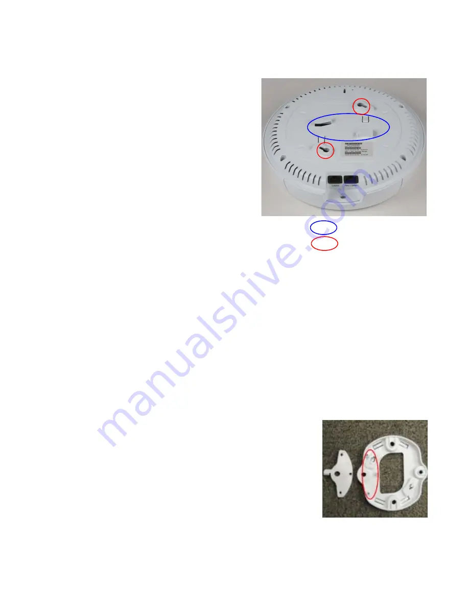
You may attach the XR-600 directly to a 15/16” 
ceiling grid without using a mounting plate. There 
are two ceiling grid tabs on the back of the XR-600, 
indicated in blue in the photo. Simply twist these 
onto the ceiling grid and proceed to Step 5 on page 9.

Direct Ceiling Mount:

To attach the XR-600 directly to the ceiling, use the 
mounting holes on the back of the XR-600, indicated 
in red in the photo. 

You need two screws of an appropriate type for the 
construction material at the mounting site. We 
suggest max screw size #8, Pan Head type.   

NOTE: The XR-600 must not be disassembled - do not remove the back of the AP to tighten the 
screws after mounting.

1.

Mark the location for the two mounting screws-3.5” (8.9 cm) apart, on center. You may 
use the 

“Direct Mounting Template” on page 13

.

2.

Install two screws in the ceiling so that they protrude 1/8” (.32 cm) between the 
mounting surface and the head of the screw.

3.

Align the holes in the back of the XR-600 over the screws protruding from the ceiling. 
Push the XR-600 chassis up on the screw heads and rotate the XR-600 to the right until it 
locks on the screw heads.    

4.

Proceed to

“Connect the Cables” on page 9

.

4B-Suspended Ceiling Grid Mount with Mounting Plate

The following steps use a mounting plate, which offers ease of 
dismount and a locking option for the AP. 

NOTE: Steps 1 and 2 are only required if you wish to lock the XR-
600 to its mounting plate after it is installed.

1.

Align the three holes in the locking plate over the 
corresponding three holes in the XR-600 mounting plate.

Ceiling Grid Clips

Screw Mount Holes

Summary of Contents for XR Series

Page 1: ...High Performance Wireless Networks XR Series Wireless Arrays QUICK INSTALLATION GUIDE XR 600 Series March 20 2014 ...

Page 2: ... Please see Legal Notices Warnings Compliance Statements and Warranty and License Agreements in the Wireless Array User s Guide All rights reserved This document may not be reproduced or disclosed in whole or in part by any means without the written consent of Xirrus Inc Part Number 812 0085 007 Rev A March 20 2014 ...

Page 3: ...ou must provide a data connection from the switch to the injector as well as another cable from the injector s OUT port to the GIGABIT1 PoE port PoGE Injectors require an AC outlet See the PoGE Installation Guide for more information Optional GIGABIT2 Connection to this second data only Gigabit port provides additional bandwidth Use Cat 5E or Cat 6 cable NOTE The XR 600 must be connected to PoGE n...

Page 4: ...th the XR Series Identify new clips by their white studs don t use old clips whose studs aren t white For a locked installation supply a zip tie small lock or other locking hardware Phillips head screwdriver to attach the wall mounting plate or ceiling locking plate to the XR 600 mounting plate Choose a Suitable Location The XR 600 can be installed on the ceiling or on a wall or may be placed on a...

Page 5: ...acket to the XR 600 mounting plate and install the XR 600 the hole in the top of the locking slug will align with the hole on the tab in the locking plate or wall bracket You can then use a customer supplied zip tie lock or other locking hardware to permanently secure the AP to the mounting plate Install Mounting Hardware and XR 600 The XR 600 can be installed directly on a normal ceiling or on a ...

Page 6: ...screws after mounting 1 Mark the location for the two mounting screws 3 5 8 9 cm apart on center You may use the Direct Mounting Template on page 13 2 Install two screws in the ceiling so that they protrude 1 8 32 cm between the mounting surface and the head of the screw 3 Align the holes in the back of the XR 600 over the screws protruding from the ceiling Push the XR 600 chassis up on the screw ...

Page 7: ...he grid s slot easiest to do at an intersection position them for the two holes in the T Bar Bracket and twist bolts till snug in the slot Secure bracket with nuts bolts pointing down Attach the Mounting Plate to bracket with supplied nuts Skip the next 2 steps 4 If using T Bar clips use the four holes on the XR 600 mounting plate to mark the placement of the four T bar clips on the metal ceiling ...

Page 8: ...cure it to the four posts using the nuts provided Tighten the nuts to 10 12 lbf ft 1 38 1 66 kgf m but do not over tighten 7 Align the two slots in the back of the XR 600 chassis shown at right 8 with the corresponding tabs in the XR 600 mounting plate shown here 9 Push the XR 600 chassis up on the mounting plate tabs and rotate the XR 600 to the right until it snaps in place 10 To secure the XR 6...

Page 9: ...the XR 600 mounting plate as shown here NOTE Only use the screws provided in the accessory kit Other screws that may appear equivalent in size may damage the XR 600 mounting plate 3 Use the four holes on the XR 600 mounting plate to mark the placement of four screws to install in the ceiling You must supply four screws of an appropriate type for your ceiling construction type 4 Drill and prepare h...

Page 10: ... wall mount bracket over the corresponding mounting plate holes NOTE Use only the screws provided in the accessory kit Other screws that seem equivalent in size may damage the mounting plate 2 Use the three screws provided in the accessory kit to attach the wall mounting plate to the XR 600 mounting plate as shown here 3 Use the Wall Mounting Bracket as a template and mark the locations on the wal...

Page 11: ...ors it is OK if it blinks If power is being properly supplied to the XR 600 the LEDs on its front will light and then commence blinking in their boot pattern GIGABIT2 Optional An additional data connection may be plugged into this port 5 Cut an access hole for the cable in the wall and draw the cable s through 6 Align the two slots in the back of the XR 600 chassis shown here with the correspondin...

Page 12: ...ity it will automatically contact Xirrus for cloud based zero touch provisioning per your settings install the latest applicable license and upgrade the AP to the latest software version as appropriate XMS Enterprise Also available as a cloud deployed solution XMS 9000 CL x This platform automatically detects and provisions new Xirrus devices deployed in your network via a similar zero touch provi...

Page 13: ...t to the slot for the locking slug opposite the side with the Gigabit ports as shown Use the reset button as follows Unplug the cable from the GIGABIT1 POE port Use a paper clip to depress the reset button there should be a faint click and hold it Plug the cable back in and continue to keep the button pressed for 10 seconds This triggers the factory default reset during the boot process 7 ...

Page 14: ...XR Series Wireless Arrays 2 12 Drawings XR 600 Mounting Bracket Wall Mounting Bracket 8 ...

Page 15: ...XR Series Wireless Arrays 3 13 Direct Mounting Template ...

Page 16: ...s Wireless Arrays 4 14 Physical Environmental Specifications Dimensions WxDxH 7 70 x 7 70 x 1 96 in 19 56 x 19 56 x 4 98 cm Weight 1 6 lb 0 73 kg Operating Temperature 0 55C 32 131F 0 90 humidity non condensing ...

Page 17: ......

Page 18: ...rporate Center Drive Thousand Oaks CA 91320 USA To learn more visit xirrus com or email info xirrus com 201 Xirrus Inc All Rights Reserved The Xirrus logo is a registered trademark of Xirrus Inc All other trademarks are the property of their respective owners Content subject to change without notice 812 0085 007 Rev A ...

Reviews: