background image


Flight Level 1

 (slider all the way down)

•  Flight Altitude 50 Meter limit

•  Flight Distance 100 Meter limit 

• Max Horizontal Speed 2 m/s

• Max Vertical Speed 2 m/s

• Attitude Mode Take off is prohibited

• GPS Flight Mode enabled

Flight Level 2

 (slider in the middle)

• Flight Altitude 120 Meter limit

• Flight Distance 300 Meter limit

• Max Horizontal Speed 6 m/s

• Max Vertical Speed 2 m/s

• Attitude Flight Mode is enabled

• GPS Flight Mode enabled

Flight Level 3

 (slider all the way to the top)

• Flight Altitude 120 Meter limit*

• Flight Distance 600 Meter limit*

• Max Horizontal Speed 8 m/s

• Max Vertical Speed 3 m/s

• Attitude Flight Mode is enabled

• GPS Flight Mode enabled 

*  

Adjustable in App Ground Station Functions and Settings on 

smart device (I.E., smart phone or tablet)

SCROLL WHEELS

•  

On the top of the transmitter, there are two scroll wheels (one 

on the left “shoulder” of the transmitter and the other on the 

right), as well as the recessed mobile device holder. 

Left 

•  The left scroll wheel is used to adjust the brightness of the 

LEDs on the Xplorer. Rolling the scroll wheel clockwise will 

brighten the LEDs; rolling the scroll wheel in a counter-

clockwise direction will decrease the brightness, and will turn 

the LEDs off altogether, if so desired.

Right 

•  The right scroll wheel is used to control the pitch of the 

camera gimbal, if applicable.

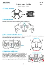
MOBILE DEVICE HOLDER

•  Situated between the two shoulder scroll wheels is the 

mobile device holder. To access this item, gently pull 

upwards in the recessed area of the holder as indicated. This 

will extend the retractable unit.

•  The top of the mobile device holder is spring-loaded and is 

capable of holding mobile devices up to 78mm X 100mm 

(3.07” x 3.94”). 

•  Insert the desired mobile device accordingly, making sure 

that the holder firmly grasps the device.

•  Adjust the mobile device holder to attain the desired position. 

When properly positioned, use the supplied wrench to 

tighten the composite joint, using care not to over-tighten. 

The wrench can be found in the “Propellers/Tools/Spare 

Parts” package.  

When flying has been completed for the day, remove the 

mobile device from the holder. Then loosen the joint and return 

the mobile device holder to the retracted position by gently 

pushing downward.

TRANSMITTER REAR 

Range Extender


If applicable, the Xplorer’s Range Extender is to be affixed to 

the rear of the transmitter. The transmitter’s Range Extender 

can be found in the “Gimbal” box. To install the Range 

Extender, position it so that the pins on the unit are located in 

the receptacles on the transmitter. After doing so, gently slide 

the Range Extender downward until it is firmly in place. 

Power Switch

Very close to the bottom/rear of the transmitter is the Power 

Switch. This switch, as the designation indicates, determines 

whether the transmitter is ON (active) or OFF. It is strongly 

suggested that the transmitter be turned ON prior to powering 

up the Xplorer. Additionally, we suggest that the user always 

ensures that the throttle stick is in the neutral (center) position 

before turning on the Xplorer.  

Carrying Handle

Near the power switch is the transmitter’s built-in carrying 

handle. This handle may also be used to allow the transmitter 

to stand upright. 

TRANSMITTER BOTTOM 

Charge Port

On the very bottom of the transmitter is the transmitter’s micro 

USB port. This port is used to charge the transmitter’s battery. 

Information about charging the transmitter is found elsewhere 

in this manual. Please refer to the appropriate section for more 

information about the charging procedure.

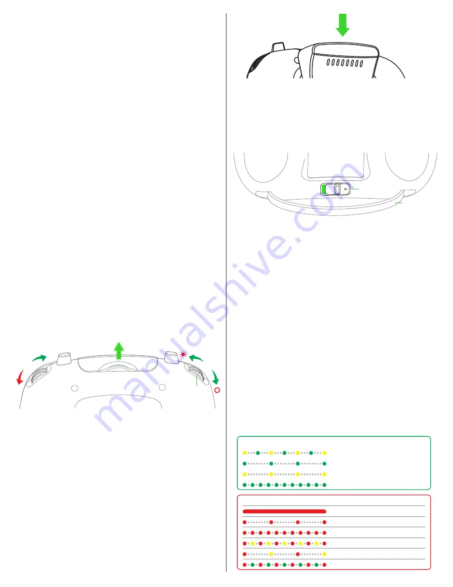
Indicator Lights on the Drone

 (Rear Flight Indicators)

The rear LEDs are used as a visual indicator of the Xplorer’s 

flight status. Please refer to the information below. 

PULL

Flight Indicators

Brightness Control

Scroll Wheel

Mobile Device Holder

Guideline

Range Extender

Power Switch

Carrying Handle

Status: Checking

GPS Flight Mode

Attitude Flight Mode

Rear Flight Indicators

Status: OK

IOC status

Gimbal connection failure

Battery: Critical (Descend slowly)


Rear Flight Indicators

Status: Not OK

Battery: Low (Return home ASAP)

GPS failure (Reboot)

Compass failure (Recalibrate)

Return Home/Disconnected with transmitter

6

Summary of Contents for Xplorer

Page 1: ...USER MANUAL V1 2 EN ...

Page 2: ...tigue KNOW BEFORE YOU FLY As a new owner of an unmanned aircraft system UAS you are responsible for the operation of this model and the safety of those around you Please contact your local authorities to find out the latest rules and regulations knowbeforeyoufly org faa gov uas FOLLOW RULES FOR SAFE OPERATION OF FPV AIRCRAFT Always follow the AMA Safety Code when operating model aircraft Visit the...

Page 3: ...green indicating that the transmitter is ready to use Please make sure that the transmitter s power switch is turned to the OFF position when charging For more information on the status of the transmitter battery please reference the Battery Indicator Information section located elsewhere in this manual Charging the Flight Battery The flight battery also might be referred to interchangeably as a S...

Page 4: ...seconds the motors will disarm stop the rotation accordingly If the left stick is moved to the left the front of the Xplorer will also rotate to the left counter clockwise Conversely moving this stick to the right will move the nose of the Xplorer in a clockwise direction The stick on the right side of the controller is responsible for moving the Xplorer forward backward and for banking angling th...

Page 5: ...e is a GPS signal available and the transmitter is in the GPS Flight Mode Auto Land With the Xplorer hovering over the desired landing point press the Auto Take off Auto Land button to activate the automatic landing function When active the green LED on the button will glow The Xplorer will then decrease the speed of the propellers and descend slowly and land as desired It is important to note tha...

Page 6: ...n be found in the Propellers Tools Spare Parts package When flying has been completed for the day remove the mobile device from the holder Then loosen the joint and return the mobile device holder to the retracted position by gently pushing downward TRANSMITTER REAR Range Extender If applicable the Xplorer s Range Extender is to be affixed to the rear of the transmitter The transmitter s Range Ext...

Page 7: ...ilver hub are meant to be attached to the corresponding brushless motor which is also marked with silver To further prevent any confusion or improper installation the diameter of the silver hub and black hub are slightly different This will prevent inadvertently attaching the incorrect propeller to a mismatched brushless motor Simply put silver to silver and black to black Additionally the propell...

Page 8: ...y from the gimbal When removed the gimbal will move freely Please be cautious so that it is not damaged XPLORER CAMERA INSTALLATION Included with the Xplorer V and available as an option item Xiro has an action camera that is capable of capturing video and still photographs The Xplorer G enables the user to install another manufacturer s camera in the supplied gimbal unit If using an action camera...

Page 9: ...d into the male fittings on the drone body The battery should be positioned so that it is flat against the body no gaps or uneven alignment Please note the indication line and text on the drone s body The battery should be installed so that the edge clearly meets this alignment indicator Step 3 With the battery firmly in place slide the battery lock button towards the battery to further secure the...

Page 10: ...t the motors For a transmitter configured for Mode 1 or Mode 2 operation both sticks have to be moved to the bottom outside corners at the same time Hold the sticks in this position until the motors are armed and the propellers begin to spin If in Modes 3 or 4 then move both sticks to the bottom inner corners Step 2 Once the motors have started release the sticks simultaneously Note You cannot sta...

Page 11: ...ght to move to the advanced Flight Training and Right again to get to Special Flight Training LOST CONNECTION FUNCTIONALITY As an added safety precaution we ve included a function that will prevent the Xplorer from performing unwanted maneuvers should it lose connection with the transmitter s control inputs The manner in which this functions is dictated by whether the pilot is using the GPS Flight...

Page 12: ... clear dry weather conditions Lighting also has a significant impact on the images and videos as well As such we suggest always flying in dry and clear weather conditions Adjust the camera settings to get the best picture by using the app FINAL CHECK BEFORE FLIGHT Are the flight battery and transmitter battery fully charged Is the smart battery mounted securely to the bottom of the Xplorer with th...

Page 13: ...turn the transmitter ON Step 4 Press the Return to Home button to change the operational mode of the transmitter observing both the Aircraft Connection and GPS LEDs Flight Modes are indicated in the diagram below Step 5 With the transmitter adjusted to the desired configuration turn the transmitter OFF This will finalize the setting Step 6 Turn ON the power once again and observe the respective LE...

Reviews: