


18
7.1.2 Status description
Status
Description
Not ready to switch on
Power on the power supply and execute the initialization procedure
Switch on disabled
Initialization end
Ready to switch on
Waiting to enter the Switch On state, the motor is not excited
Switch on
VFD is ready, main loop power supply is normal
Operation enabled
VFD can be controlled and work normally
Fault reaction active
Occur the error and the cause of the fault needs to be determined
Fault
Fault status
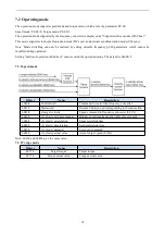
7.1.3 Control command
The status is controlled by the bit of the control command (Controlword 6040 h). The combined control table is as
follows.
Command
Controlword
Transitions
Bit7
Bit3
Bit2
Bit 1
Bit 0
Fault
reset
Enable
Operation
Quick
Stop
Enable
Voltage
Switch
On
Switch on
0
-
1
1
0
2,6,8
Switch on+
Enable operation
0
0
1
1
1
3
Disable voltage
-
1
1
1
1
3,4 (Automatic
conversion)
Quick stop
-
-
-
0
-
7,9,10
Disable operation
-
0
1
1
1
5
Enable operation
-
1
1
1
1
4
Fault reset
0->1
-
-
-
-
15
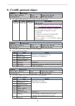
7.1.4 Status
The bit combination of statusword (6041 hex) indicates the working status of the equipment, as shown in the
following table:
Status
Bit 12
FC
Bit 9
RO
Bit 6
SOD
Bit5
QS
Bit 4
VE
Bit 3
F
Bit 2
OE
Bit 1
SO
Bit 0
RTSO
Not ready to switch
on
1
1
0
0
-
0
0
0
0
Switch on disable
1
1
1
-
-
0
0
0
0
Ready to switch on
1
1
0
1
-
0
0
0
1
Switched on
1
1
0
1
1
0
0
1
1
Operation enabled
1
1
0
1
1
0
1
1
1
Fault reaction active
1
1
0
1
-
1
1
1
1
Fault
1
1
0
1
-
1
0
0
0
Note:
(1)FC = Follow command; RO = Remote; SOD = Switch on disabled; QS = Quick stop; VE = Voltage enabled;
F = Fault; OE = Operation enabled; SO = Swicthed on; RTSO = Ready to switch on.
(2)"-" means no requirement, which may be 0 or 1. It does not participate in the judgment.


