


Configuration options
31
Configuration options
The FPGA of the XtremeDSP Spartan-3A DSP Development Board can be configured by four major devices:
•
Xilinx download cable (JTAG)
•
System ACE controller (JTAG)
•
Board flash memory
•
SPI flash memory
The following section provides an overview of the possible ways the FPGA can be configured.
JTAG configuration
The FPGA, board’s flash memory, and CPLD can all be configured through the JTAG port of the XtremeDSP
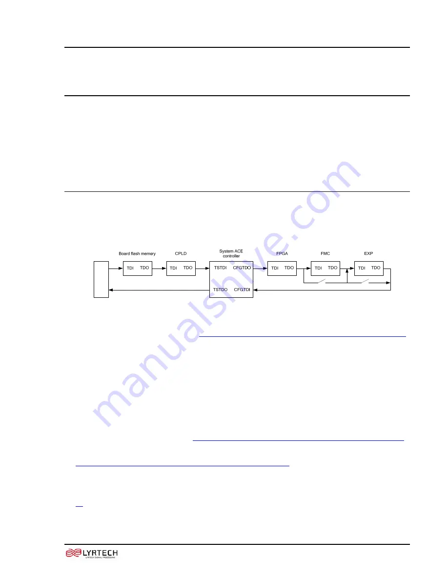
Spartan-3A DSP Development Board. The JTAG chain of the board is illustrated below.
JT
AG hea
der
Figure 5 XtremeDSP Spartan-3A DSP Development Board JTAG chain
The chain starts at the JTAG header (see
XtremeDSP Spartan-3A DSP Development Board parts and functions
)
and goes through the System ACE controller, the board flash memory, the FPGA, the CPLD and the FMC
expansion connector. The chain bypasses the FMC expansion connector if there is no expansion module present.
JP4 jumper must not be populated for appropriate JTAG operation.
The JTAG chain can be used to program the FPGA and access the FPGA for hardware and software
troubelshooting.
The JTAG header’s connection to the JTAG chain allows a host computer to transfer bitstreams to the FPGA
using iMPACT from Xilinx. The JTAG header also allows such troubleshooting tools as ChipScope Pro to
access the FPGA.
The System ACE controller can also program the FPGA through the JTAG port. By inserting a CompactFlash
card in the CompactFlash reader (see
XtremeDSP Spartan-3A DSP Development Board parts and functions
configuration information can be stored and programmed on the FPGA. The System ACE controller supports up
to eight configuration images that can be selected using the three configuration address DIP switches (see
XtremeDSP Spartan-3A DSP Development Board parts and functions
). Under the control of the FPGA, the
System ACE controller can be instructed use any of the eight configuration images.
The configuration mode should be set to 101 (ACE_CFGADDR0_IN (OFF), ACE_CFGADDR1_IN (ON),
ACE_CFGADDR2_IN (OFF) and ACE_CFG_EN should be OFF to use System ACE configuration (see item
, above).


