


SP605 Hardware User Guide
www.xilinx.com
43
UG526 (v1.1.1) February 1, 2010
Detailed Description
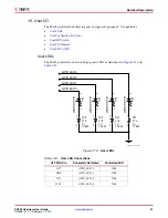
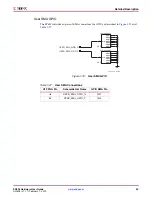
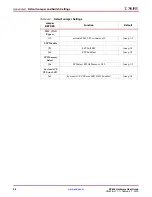
User DIP Switch
The SP605 includes an active-High four-pole DIP switch, as described in
Figure 1-17
and
Table 1-25
. Three poles (switches 1-3) are pulled up to 2.5V, and one pole (switch 4) is
pulled up to 1.5V, when closed.
X-Ref Target - Figure 1-17
Figure 1-17:
User DIP Switch S2
Table 1-25:
User DIP Switch Connections
U1 FPGA Pin
Schematic Net Name
DIP Switch Pin
C18
GPIO_SWITCH_0
S2.1
Y6
GPIO_SWITCH_1
S2.2
W6
GPIO_SWITCH_2
S2.3
E4
GPIO_SWITCH_3
S2.4
VCC2V5
VCC1V5_FPGA
1
2
3
4
1234
8
7
6
5
S
2
ON
S
DMX-4-X
GPIO_
S
WITCH_3
GPIO_
S
WITCH_2
GPIO_
S
WITCH_1
GPIO_
S
WITCH_0
1
2
R225
1.00K
1/16W
1%
2
1
1%
1/16W
1.00K
R224
1
2
R223
1.00K
1/16W
1%
2
1
1%
1/16W
1.00K
R222
UG526_17 _102609


