


34
www.xilinx.com
SP605 Hardware User Guide
UG526 (v1.1.1) February 1, 2010
Chapter 1:
SP605 Evaluation Board
1
3
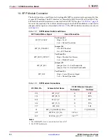
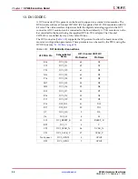
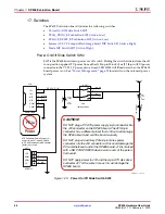
. DVI CODEC
A DVI connector (P3) is present on the board to support an external video monitor. The
DVI circuitry utilizes a Chrontel CH7301C (U31) capable of 1600 X 1200 resolution with 24-
bit color. The video interface chip drives both the digital and analog signals to the DVI
connector. A DVI monitor can be connected to the board directly. A VGA monitor can also
be connected to the board using the supplied DVI-to-VGA adaptor. The Chrontel
CH7301C is controlled by way of the video IIC bus.
The DVI connector (
Table 1-18
) supports the IIC protocol to allow the board to read the
monitor's configuration parameters. These parameters can be read by the FPGA using the
DVI IIC bus (see
“14. IIC Bus,” page 35
).
Table 1-18:
DVI Controller Connections
U1 FPGA Pin
Schematic Net
Name
U31 Chrontel CH7301C
Pin Number
Pin Name
K16
DVI_D0 63
D0
U19
DVI_D1 62
D1
T20
DVI_D2 61
D2
N16
DVI_D3 60
D3
P16
DVI_D4 59
D4
M17
DVI_D5 58
D5
M18
DVI_D6 55
D6
R15
DVI_D7 54
D7
R16
DVI_D8 53
D8
P17
DVI_D9 52
D9
P18
DVI_D10 51
D10
R17
DVI_D11 50
D11
J17
DVI_DE 2
DE
J16
DVI_H 4
H
L15
DVI_RESET_B 13
RESET_B
B22
DVI_V 5
V
C22
DVI_XCLK_N 56
XCLK_N
C20
DVI_XCLK_P 57
XCLK_P
No Connect
DVI_GPIO0
8
GPIO0
D22
DVI_GPIO1
7
GPIO1


