background image

Ethernet 1000BASE-X PCS/PMA or SGMII v7.0

www.xilinx.com

49

UG145 January 18, 2006

SGMII Example Design / Dynamic Switching Example Design

R

Demonstration Test Bench

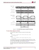
Figure 4-12

 illustrates the demonstration test bench for the Ethernet 1000BASE-X 

PCS/PMA or SGMII Core in SGMII mode.

The demonstration test bench is described in the following files:

VHDL

project_dir>

/

<component_name>

/simulation/

demo_tb.vhd

Verilog

project_dir>

/

<component_name>

/simulation/

demo_tb.v

The demonstration test bench is a simple VHDL or Verilog program to exercise the 
example design and the core itself. The demonstration test bench performs the following 
tasks.

Input clock signals are generated.

A reset is applied to the example design.

The Ethernet 1000BASE-X PCS/PMA core is configured through the MDIO interface 
by injecting an MDIO frame into the example design. This disables Auto-Negotiation 
and takes the core out of Isolate state.

The following frames are injected into the GMII transmitter by the GMII stimulus 
block at 1 Gbps.

Figure 4-12:

Demonstration Test Bench for the Ethernet 1000BASE-X PCS/PMA or 

SGMII Core in SGMII Mode

PMA

Monitor

(serial to parallel

conversion and

8B10B 

decoding)

PMA

Stimulus

(8B10B encoding

and parallel to

serial 

conversion)

GMII

Stimulus

GMII

Monitor

GMII

RocketIO

DUT

Demonstration Testbench

Control and data structures

Configuration

Stimulus

Summary of Contents for LogiCORE

Page 1: ...R LogiCORE Ethernet 1000BASE X PCS PMA or SGMII v7 0 Getting Started Guide UG145 January 18 2006...

Page 2: ...REE THAT YOU HAVE NOT RELIED ON ANY ORAL OR WRITTEN INFORMATION OR ADVICE WHETHER GIVEN BY XILINX OR ITS AGENTS OR EMPLOYEES XILINX MAKES NO OTHER WARRANTIES WHETHER EXPRESS IMPLIED OR STATUTORY REGAR...

Page 3: ...tarted Guide UG145 January 18 2006 The following table shows the revision history for this document Date Version Revision 09 30 04 1 0 Initial Xilinx release 04 28 05 2 0 Updated to version 6 0 of the...

Page 4: ...www xilinx com Ethernet 1000BASE X PCS PMA or SGMII v7 0 UG145 January 18 2006...

Page 5: ...or SGMII Core 14 Document 14 Chapter 2 Installing and Licensing the Core System Requirements 15 Before You Begin 15 Installing the Core 15 CORE Generator IP Updates Installer 16 Manual Installation 1...

Page 6: ...iver 33 Transmitter Elastic Buffer 33 Demonstration Test Bench 34 Customizing the Test Bench 35 Core Example Design with Ten Bit Interface 36 Example Design Top Level HDL 36 Transmitter Elastic Buffer...

Page 7: ...BASE X PCS PMA using RocketIO 32 Figure 4 4 Demonstration Test Bench Using RocketIO 34 Figure 4 5 Example Design Top Level HDL for the Ethernet 1000BASE X PCS with TBI 36 Figure 4 6 Demonstration Test...

Page 8: ...8 www xilinx com Ethernet 1000BASE X PCS PMA or SGMII v7 0 UG145 January 18 2006 R...

Page 9: ...rovides information about installing and licensing the core Chapter 3 Quick Start Example Design provides instructions to quickly generate the core and run the example design through implementation an...

Page 10: ...om xlnx xil_tt_home jsp Resource Description URL Convention Meaning or Use Example Courier font Messages prompts and program files that the system displays speed grade 100 Courier bold Literal command...

Page 11: ...k_name loc1 loc2 locn Notations The prefix 0x or the suffix h indicate hexadecimal notation A read of address 0x00112975 returned 45524943h A _n means the signal is active low usr_teof_n is active low...

Page 12: ...12 www xilinx com Ethernet 1000BASE X PCS PMA or SGMII v7 0 UG145 January 18 2006 Preface About This Guide R...

Page 13: ...ce Although the Ethernet 1000BASE X PCS PMA or SGMII core is a fully verified solution the challenge associated with implementing a complete design varies depending on the configuration and functional...

Page 14: ...gns that do not follow these guidelines Feedback Xilinx welcomes comments and suggestions about the Ethernet 1000BASE X PCS PMA or SGMII core and the documentation supplied with the core Ethernet 1000...

Page 15: ...Professional with Service Pack 1 Solaris Linux Sun Solaris 8 9 Red Hat Enterprise Linux 3 0 32 bit and 64 bit Software Xilinx ISETM 8 1i Before You Begin Before installing the core you must have a Xi...

Page 16: ...stall_history Note that this step assumes your Xilinx software is installed in C Xilinx Manual Installation 1 Close the CORE Generator application if it is running 2 Download the IP Update ZIP file fr...

Page 17: ...of the cores choose an option from the Show drop down list at the top of the window Latest Versions Display the latest versions of all cores All Versions Display all versions of cores including new co...

Page 18: ...ining Your License Note Because the Simulation Only Evaluation license is provided with the CORE Generator no action is required Obtaining a Full License To obtain a Full license you must register for...

Page 19: ...ter 4 Detailed Example Design Overview The Ethernet 1000BASE X PCS PMA example design consists of Ethernet 1000BASE X PCS PMA core netlist Example design HDL top level and associated HDL files Demonst...

Page 20: ...ct 3 For project options select the following A VirtexTM II Pro part to generate the default Ethernet 1000BASE X PCS PMA core In the Design Entry section select VHDL or Verilog then select Other for V...

Page 21: ...nd place and routes the example design The script then creates gate level netlist HDL files in either VHDL or Verilog along with associated timing information SDF files Simulating the Example Design S...

Page 22: ...Verilog A timing simulation model is generated when run through the Xilinx tools using the implementation script You must implement the core before attempting to run timing simulation To run a VHDL o...

Page 23: ...component_name is the component name as entered in the core customization window Note The implement and simulation timing directories are only present with a Full license Figure 4 1 Core Directories...

Page 24: ...tput products component_name _flist txt A test file listing all of the output files produced when a customized core is generated by CORE Generator project_dir component_name gig_eth_pcs_pma_v7_0_relea...

Page 25: ...ectory is produced by the implementation scripts and is used to run through the example design and the core through the Xilinx implementation tools Once the implement script has completed it contains...

Page 26: ...It is called by the simulate_ncsim sh script file project_dir component_name simulation timing Note This directory is only present with the Full license simulate_mti do A ModelSim macro file that comp...

Page 27: ...sed to generate a core An XCO file is generated by the CORE Generator for each core that it creates in the current project directory An XCO file can also be used as an input to the CORE Generator comp...

Page 28: ...n This directory contains the support files necessary for a Verilog implementation of the example design component_name _top v This file is the top level Verilog file for the example design Other Veri...

Page 29: ...he following sections in this document for more information Core Example Design Using RocketIO page 32 Core Example Design with Ten Bit Interface page 36 SGMII Example Design Dynamic Switching Example...

Page 30: ...erforms the following steps 1 The HDL example design files are synthesized using XST 2 Ngdbuild is run to consolidate the core netlist and the example design netlist into the NGD file containing the e...

Page 31: ...on Timing simulation Note This script is only present with the Full license The test script is a ModelSim or an IUS macro that automates the simulation of the test bench It is located at project_dir c...

Page 32: ...ponent_name _top v The example design HDL top level contains the following An instance of the Ethernet 1000BASE X PCS PMA core An instance of a Virtex II Pro or Virtex 4 RocketIO transceiver Clock man...

Page 33: ...r component_name example_design cal_block_v1_2_1 vhd Verilog project_dir component_name example_design cal_block_v1_2_1 v Transmitter Elastic Buffer The Transmitter Elastic Buffer is described in the...

Page 34: ...e simulation demo_tb v The demonstration test bench is a simple VHDL or Verilog program to exercise the example design and the core itself Core with MDIO Interface The demonstration test bench perform...

Page 35: ...test bench performs the following tasks Input clock signals are generated A reset is applied to the example design The Ethernet 1000BASE X PCS PMA core is configured using the Configuration Vector to...

Page 36: ...ted the core can be reconfigured by editing the injected MDIO frame in the demonstration test bench See the Xilinx LogiCORE Ethernet 1000BASE X PCS PMA or SGMII User Guide for more information on usin...

Page 37: ...c Buffer is described in the following files VHDL project_dir component_name example_design tx_elastic_buffer vhd Verilog project_dir component_name example_design tx_elastic_buffer v When the GMII is...

Page 38: ...am to exercise the example design and the core itself Core with MDIO Interface The demonstration test bench performs the following tasks Input clock signals are generated A reset is applied to the exa...

Page 39: ...nfigured via the Configuration Vector to take the core out of the Isolate state The following frames are injected into the GMII transmitter by the GMII stimulus block the first is a minimum length fra...

Page 40: ...ORE Ethernet 1000BASE X PCS PMA or SGMII User Guide for more information about using the MDIO interface If the MDIO interface option has not been selected the core can be reconfigured by modifying the...

Page 41: ...ster instances where required Input and output buffers for other port signals of the example design top level The example design HDL top level connects the GMII of the core to the SGMII adaptation mod...

Page 42: ...e core 100 times This GMII style interface is not a standard interface true GMII only operates at a clock frequency of 125 MHz but it does allow a straightforward internal connection to an Ethernet MA...

Page 43: ...100 Mbps speeds At 1 Gbps sgmii_clk_r is fixed at logic 0 sgmii_clk_f is fixed at logic 1 sgmii_clk_r is connected to the rising edge triggered flip flop of an IOB output DDR clocked with clk125m sgm...

Page 44: ...0BASE X PCS PMA or SGMII v7 0 UG145 January 18 2006 Chapter 4 Detailed Example Design R sgmii_clk This clock enable signal is used as the control for the data byte repetition in the Transmitter and Re...

Page 45: ...following files VHDL project_dir component_name example_design sgmii_adapt johnson_cntr vhd Verilog project_dir component_name example_design sgmii_adapt johnson_cntr v Figure 4 9 Clock Generator Out...

Page 46: ...This module accepts transmitter data from the GMII style interface from the attached client MAC and samples the input data on the 125 MHz reference clock clk125m This sampled data can then be connecte...

Page 47: ...t 1000BASE X PCS PMA or SGMII core This data is sampled and sent out of the GMII receiver interface for the attached client MAC The 1 Gbps and 100 Mbps cases are illustrated in Figure 4 11 At 1 Gbps t...

Page 48: ...e Adaptation module also performs a second function that accounts for the latency inferred in Figure 4 11 The 8 bit Start of Frame Delimiter SFD code is detected and if required it is realigned across...

Page 49: ...he demonstration test bench performs the following tasks Input clock signals are generated A reset is applied to the example design The Ethernet 1000BASE X PCS PMA core is configured through the MDIO...

Page 50: ...ted in both stimulus and monitor functions Changing Frame Error Status Errors can be inserted into any of the predefined frames in any position by setting the error field to 1 in any column of that fr...

Page 51: ...xilinx com 51 UG145 January 18 2006 SGMII Example Design Dynamic Switching Example Design R 100 Mbps operation set speed_is_10_100 to logic 1 set speed_is_100 to logic 1 10 Mbps operation set speed_is...

Page 52: ...52 www xilinx com Ethernet 1000BASE X PCS PMA or SGMII v7 0 UG145 January 18 2006 Chapter 4 Detailed Example Design R...

Reviews: